Q&A
Control Units
BB
![]()
The total output power, is the sum total of power being output at the same time on channel 1 and channel 2, and it can reach a maximum of 28W
(maximum power for each single channel also amounts to 28W).
QA No. 11-0100
![]()
We cannot guarantee that power restarting can be performed within less than 2 seconds.
Please perform ON/OFF controlling using the control terminal.
QA No. 11-0076
![]() Can 2 interface units be used for 1 BB Series master unit and 7 or less slave units?
Can 2 interface units be used for 1 BB Series master unit and 7 or less slave units?
![]()
They cannot be used.
The 2nd connected interface unit cannot be used to control the Control Unit of the 8 or less units (1 master unit and 7 slave units or less).
Since each single slave interface unit will be allocated to channels 1 through 8, even if a 2nd interface unit is used, it would be necessary to add a 9th unit.
QA No. 11-0075
![]() What is the light-emitting delay for the BB Series during ON/OFF switching using the terminal block?
What is the light-emitting delay for the BB Series during ON/OFF switching using the terminal block?
![]()
It will be the same as for STU mode (3μs).
QA No. 11-0074
![]()
After receiving the dimming settings write (WR) signal, a maximum of 30ms is required before the dimming settings are applied (as listed in the user manual).
Regarding the 2nd channel, since the signal cannot be processed within the maximum 30ms time frame mentioned above, the 2nd channel signal can only be processed after an amount of time equivalent or longer than the 30ms maximum after WR signal is first received.
As a result, in order for dimming settings application to be completed for the 2 channel signal, a minimum of (30ms+α) × 2 = 60ms is necessary.
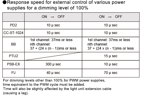
The maximum time necessary for dimming settings to be applied is 37msec.
QA No. 11-0073
![]() What factors can cause a "b error" for the BB Series?
What factors can cause a "b error" for the BB Series?
![]()
The worst case scenario that can cause this is repeated disconnection of the master and slaves while power is being supplied.
For such cases, communication part damage has occurred, and it is likely that the master, slaves, or both will need to replaced.
Please contact one of our various sales offices.
QA No. 11-0072
![]() What can be done to deal with the occurrence of a "b error" for the BB Series?
What can be done to deal with the occurrence of a "b error" for the BB Series?
![]()
- Perform a hardware reset
- Perform the recovery command
- Check the ID configuration switches to make sure there are no duplicate IDs
- Check the terminating unit
If the above 4 steps have been performed and the system still doesn't recover, separate the individual units, and try to determine which individual unit is causing the issue.
Once the offending unit has been identified, please contact one of our various sales offices.
QA No. 11-0071
![]()
In the specifications it is listed at 3μs or less, and the actual measured performance is 1μs or less.
QA No. 11-0070
![]()
Regardless of the channel order, there will be a maximum 32ms delay between each unit.
If 7 units are connected, the 7th unit will have a maximum delay of 224ms.
QA No. 11-0069
![]()
When performing trigger light-emitting, the only thing that can be externally controlled is the PWM duty cycle, and the width of the light-emitting interval cannot be controlled. In order to change light-emitting interval width configurations, the panel should be used for performing settings, and a copy command needs to be executed.
If settings are not performed, the default value of 0.1ms is read and used.
QA No. 11-0068
![]()
Using the master and slave unit options, please set interface unit ON/OFF switching to enabled.
(Since terminal block switching is set to enabled by default.)
QA No. 11-0067
![]() We are currently using the PTU2 Series, but what would happen if we replace it with the BB Series?
We are currently using the PTU2 Series, but what would happen if we replace it with the BB Series?
![]()
If you are making use of the same number of units as the number of channels being used while also performing external control, you will need to acquire a separate interface unit.
QA No. 11-0066
![]() How do we check the strobe light-emission timing when using a BB Series unit?
How do we check the strobe light-emission timing when using a BB Series unit?
![]()
Light-emission timing can only be checked by inputting an external timing signal.
Please note, however, that it is possible to check light-emission interval width by checking the internal light-emission mode.
QA No. 11-0065
![]()
The setting values that have been configured from the I/F unit are stored in each individual Control Unit.
However, since switching to EXT mode can only be performed from the I/F unit, if light-emission based on the stored setting values is necessary, an I/F unit must be used.
QA No. 11-0064
![]() How can the BB Series unit be connected when using lighting that exceeds 30W?
How can the BB Series unit be connected when using lighting that exceeds 30W?
![]()
It is not possible to connect lighting that consumes 30W or more to a single connector.
QA No. 11-0063
![]()
In some cases, changes can be made to cable length and cable type as part of a custom order. Please inquire further with our sales representatives.
QA No. 11-0062
![]() How should the BB Series unit be cleaned if it gets soiled?
How should the BB Series unit be cleaned if it gets soiled?
![]()
Cleaning of units using volatile oils is prohibited.
When performing cleaning, please use industrial alcohol.
QA No. 11-0061
![]() What is the BB Series unit's product design service life?
What is the BB Series unit's product design service life?
![]()
It is 4 years (projected capacitor service life).
QA No. 11-0060
![]() How should a fan cable be connected when using the BB Series unit?
How should a fan cable be connected when using the BB Series unit?
![]()
The unit is not equipped with a fan connector.
We ask that you provide a separate Control Unit to drive any fans.
QA No. 11-0059
![]()
That is correct.
For the BB power supplies, the ratio of light-emission interval width to time during which trigger signal reception is disabled is 1:16.
For the PTU2, the ratio of light-emission interval width to time during which trigger signal reception is disabled is 1:14.2.
QA No. 11-0058
![]() We are currently using the ILA-2000, 4000. Is it possible to use them with BB Series units?
We are currently using the ILA-2000, 4000. Is it possible to use them with BB Series units?
![]()
They cannot be used with the ILA Series.
QA No. 11-0056
![]()
Based on the specifications, the protection circuit is designed to activate when power consumption reaches 110% of the rated amount.
Please also note that there exists lighting that is listed as consuming 30W, but which does not consume 30W in actual use (due to rounding up).
QA No. 11-0055
![]()
The reason that the supplied cable is connecting these open pins is simply to provide mechanical strength.
Since there is nothing electrically connected to the open pins, there is no problem.
QA No. 11-0054
![]()
Linearity is not the same. There are minor differences.
QA No. 11-0053
![]()
There is no correlation.
QA No. 11-0052
![]()
There is no problem in performing common grounding, however, from a noise prevention perspective, it is recommended that the (-) side grounding is performed independently for the individual terminals.
QA No. 11-0051
![]()
There is no conversion cable.
QA No. 11-0055
![]() We are using a BB Series PWM type unit, and light is not being emitted when the unit is powered on.
We are using a BB Series PWM type unit, and light is not being emitted when the unit is powered on.
![]()
The light is not turning on because the default dimming value is set to 0.
If the dimming value is changed, the light will turn on.
QA No. 11-0049
![]()
A "Err6" error will be triggered when the input voltage falls to roughly 16V.
When an "Err6" error occurs, the unit will turn off the light unit.
QA No. 11-0048
![]()
Although the "Err1" error indicates a short to ground, this condition will not occur at terminals or signal lines that are exposed to the user, such as the front-side terminals, etc.
This may occur for example in cases where a metallic part, etc., has entered the inside of the unit's chassis.
If an "Err1" error occurs, light units will automatically be turned off. In order to perform recovery, rectify the problem, and perform the key operations for the initialization procedure (if the same error occurs during initialization process, light units will be automatically turned off and an error will be displayed).
QA No. 11-0047
![]() When using a BB Series unit, what will happen if an ID is changed while the main power is turned ON?
When using a BB Series unit, what will happen if an ID is changed while the main power is turned ON?
![]()
If IDs are changed during operation, subsequent normal operation cannot be guaranteed.
We ask that you do not change IDs during operation.
QA No. 11-0046
![]()
It cannot be used.
QA No. 11-0045
![]()
For example, if channel 1 (200) and channel 2 (50) is increased by 100%, this will result in a change of channel 1 (255) and channel 2 (100)
(although internally, channel 1 will be recognized as 400).
If this is then decreased by 10%, this will result in a change of channel 1 (255) and channel 2 (90), and a subsequent 90% decrease will result in channel 1 (200) and channel 2 (50).
If the ALL selection feature is enabled, the dimming values for the individual channels will be configured as follows:
For an arbitrary channel "y," the dimming value for channel "y" =
dimming value for channel "y" + dimming value for channel "y" x "percent value."
QA No. 11-0044
![]() When using a BB Series unit, what is the dielectric input strength of the terminal block?
When using a BB Series unit, what is the dielectric input strength of the terminal block?
![]()
26.4V when insulated by a photo coupler.
QA No. 11-0043
![]()
It cannot be synchronized.
QA No. 11-0042
![]() When using a BB Series unit, what is the maximum delay time in STU mode?
When using a BB Series unit, what is the maximum delay time in STU mode?
![]()
There is a maximum delay of 3μs.
QA No. 11-0041
![]() When using a BB Series unit, can PWM be synchronized in STU mode?
When using a BB Series unit, can PWM be synchronized in STU mode?
![]()
It can be synchronized.
QA No. 11-0040
![]()
The lock will be disengaged.
QA No. 11-0039
![]()
On a fundamental level, this is possible.
However, since the response time for the 1st channel is 37msec, and for the nth channel, 37 + (24 x (n-1))msec will be required, we recommend controlling it from the terminal block.
QA No. 11-0038