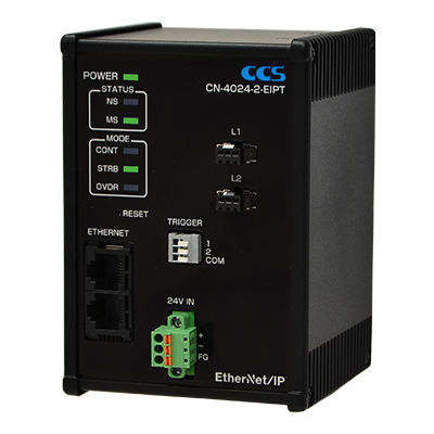
CN Series
Download Pamphlet PDF
Features
Best Fit for Inspection Systems on EtherNet/IP Networks
Conforms to ODVA Composite Conformance Test Revision CT15.A smart device for the IoT era
You can get the following values through an EtherNet/IP network:
Accumulated trigger count, accumulated lighting duration,and error status
Additionally, you can set and check the following values:
Lighting mode, trigger logic, ON/OFF setting for the Light Unit, light intensity, strobe time, and lighting delay
The CN Controller also provides TCP/IP commands for the same operations.

Note: The CN Controller is operated only through external control, and cannot be controlled manually.
Easy Installation
We will offer an Electronic Data Sheet (EDS) file which describes the communications configuration of the device. Registering the EDS file to a PLC automation system reduces labor and time required for setting up the device.

Easy Operation
When you use a PLC ladder editor, you can get and set the operation values for the CN Controller.

We offer sample files for PLC programs to support easy operation. The available files are for Rockwell (1769-L16ER-BB1B) and Omron (NX1P2-1040DT).
Operation Data Output
The following values can be obtained for system operation: Accumulated trigger count which counts the number of Light Unit ON operations, accumulated lighting duration which counts the total period that the Light Unit is ON in hours, and error status.
DLR Function
The CN Controller is equipped with the Device Level Ring (DLR) function.
Connect two LAN cables to the CN Controller, and if a communications error occurs, the CN Controller will change the communications route immediately.
(Refer to the illustration on the right page.)

Three Selectable Lighting Modes
1. Overdrive Mode
(48 VDC output, Strobe time control: 1 to 1,000 μs, Maximum duty ratio: 7%)
When an external trigger signal is input to the CN Controller, the corresponding Light Unit flashes.
By overdriving the voltage that is applied to the Light Unit, you can make the Light Unit flash a few times brighter than when the Light Units operate in any other lighting modes.
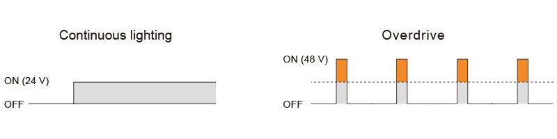
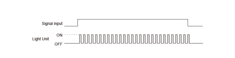
2. Strobe Mode
(24 VDC Output, Strobe time control: 1 to 10,000 μs)
When an external trigger signal is input to the CN Controller, the corresponding Light Unit flashes.
LED Lights can withstand being turned on and off frequently. Turning on the Light Unit only when taking images will reduce heat generation, provide a more stable radiation output, and increase the service life of the Light Unit.

3. Continuous Mode
(24 VDC Output, PWM Control: the light intensity can be set to any of 512 levels. )
The Light Unit will be ON (or OFF) as long as there is an external trigger signal input to the CN Controller.
Video
Watch the video below.
How to Check Lighting Connection Combinations
Make sure that the total input current of the connected Light Units is no more than the output current of the Control Unit.
Contact your sales representative for details.
Support Tools
| EDS File | The identity information required to recognize CN-4024-2-EIPT. ODVA compliant.< |
|---|---|
| Initial setup | You can set the IP address of CN-4024-2-EIPT with this program.< |
| PLC Projects | Sample files for PLC programs to support easy operation. The available files are for Rockwell (1769-L16ER-BB1B) and Omron (NX1P2-1040DT) |
- Please check "System Requirements for Product Applications" for the system requirements of this program.
- The application can be downloaded from "Product Lineup"
Products
-
Machine Vision Applications
Ring
Low-angle Ring
Waterproof Ring
Bar (Area)
Low-angle Square
Flat
Flat Dome
Line Pattern
Dome
Coaxial
Cylinder
High Power Strobe
UV Lights [Ultraviolet Lighting] / Violet Light
IR Lights [Infrared Lighting] (under 1000nm)
IR Lights [Infrared Lighting] (over 1000nm)
Spot
Fiber Heads
Light Source Unit
Line (Convergent Lighting)
Line (Diffused Lighting)
Line (Oblique Angled Lighting)
Reference Light Source
Lights for Fringe Interference Inspection
Custom Order Product
Intensity Control Units [Light Units with Intensity Control Unit ]
Effilux Products
Basler Camera Light Series
- BCL Series (Bar Light)
- BCR Series (Ring Light)
- BCBL Series (Flat Light)
- BCF Series (Flood Light)
- BCL Series (Bar Light) Diffusion Plates
- BCR Series (Ring Light) Diffusion Plates
- BCF Series (Flood Light) Transparent Plate
- BCL Series (Bar Light) Light Polarizing Plates
- BCR Series (Ring Light) Polarizing Plates
- BCF Series (Flood Light) Polarizing Plates
- BCR Series (Ring Light) Light Adapter
- BCL Series (Bar Light) Light Bracket
- Basler Camera Light dedicated cable
-
Control Units
Digital Control Units
Strobe Unit
High Power Strobe Control Unit
PoE Enabled Controller
Controller with EtherNet/IP Interface
LED Light Controller
Control Units [for the HLV Series]
High-capacity Constant-current Control Units
High-capacity Analog Control Unit
Control Units [for CCS AItec]
-
Cables
Straight Cables
2-way Cables
4-way Cables
Robot Cables
2-way Robot Cables
4-way Robot Cables
Straight Cables [EL connector type]
2-way Cables [EL connector type]
Extension Cable [for PF Series]
Straight Cables for metal connector (7 pins)
Straight Cables for metal connector (37 pins)
Straight Cables for M12 connector
External Control Cables
Relay Connector
AC Power Cable
-
Options
Filters
Diffusion Plates
- Diffusion Plates [for Ring Lights]
- Diffusion Plates [for LDR-PF Series]
- Diffusion Plates [for LDR-PF-LA Series]
- Diffusion Plates [for Low-angle Ring Lights]
- Diffusion Plates [for Bar Lights]
- Diffusion Plates [for LDL-PF Series]
- Diffusion Plates [for HLDL3 Series]
- Diffusion Plates [for LB Series]
- Diffusion Plates [for Coaxial Lights]
- DF Series
- DF80 Series
Polarizing Plates
- Polarizing Plates [for Ring Lights]
- Polarizing Plates [for LDR-PF Series]
- Polarizing Plates [for Bar Lights]
- Polarizing Plates [for LDL-PF Series]
- Polarizing Plates [for HLDL3 Series]
- Polarizing Plates [for LB Series]
- Polarizing Plates [for Coaxial Lights]
- Polarizing Plates [for IR Series Infrared Lights (over 1000-nm type)]
- PL Series (FASTUS)
Light Control Films
Protective Plates
Adapter [for the CSR Series]
Lens Attachment Rings
Fixtures
Fixtures
Converter
Coaxial Units
Reflection Plate
Condenser lens
-
Lenses
Telecentric Lenses
Macro Lenses
-
Software Tools
Program for controllers
Version Upgrade for controllers
Application note for controllers
-
Agri-Bio Lighting
LED Light Units for Plant Research
ISL-150X150 Series Unit
ISL-150X150 series cables
-
Human Vision Inspection and Microscope Applications
LED Light Units for Microscopes
 Request Free Trial
 Request Quotation
 Inquiry Form
 Locations