POD Series
Strobe lighting.
Overdrive specifications.
Voltage control is allowed during the overdrive operation.
Download Pamphlet PDF
Features
- Strobe lighting. Overdrive specifications.
- Voltage control during overdrive operation.
- Strobe time control
- Strobe time: 1 to 1,000 μs (in steps of 1 μs)
- Strobe delay: 0 to 1,000 μs (in steps of 1 μs)
- You can individually control both brightness and flash duration.
- Ethernet and parallel communications
- Continuous lighting under PWM control
- Storable Scenes
- Two channels
- Sets of parameters related to light control can be registered.
- The light intensity can be set to one of 512 levels. Output voltage: 24 to 48 VDC
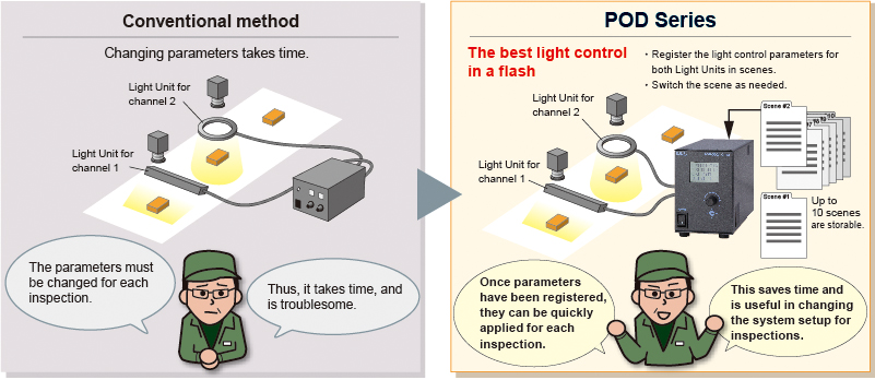
Registering Scenes (sets of parameters)

You can register sets of parameters called scenes that consist of the light control settings for the two channels.
By just applying a scene to the channels, you can easily change the settings. Up to 10 scenes can be registered. Refer to the Instruction Guide for details.
Compatible with More Than 700 Models Light Units
These Light Units support strobe lighting using overdrive. They emit light brighter than that of continuous lighting.
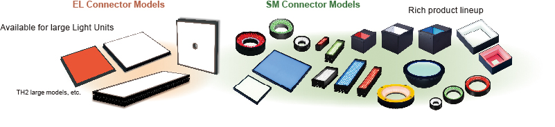
For information on possible combinations of Light Units with a POD-series Control Unit, refer to POD-5024-2-PEI.
What Is "Overdrive"?
Overdrive is used to emit brighter light by applying a high voltage to an LED Light Unit only for flashes shorter than 1 ms. This voltage exceeds the voltage for continuous lighting.
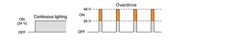
* The output characteristics and light intensity setting values for starting light emission vary with the combinations of light units and power supplies.
POD-22024-4-PEI

Strobe time
For manual control and Ethernet communications:
1 to 1,000 μs(in steps of 1 μs)1,002 to 3,000 μs(in steps of 3 μs)
For parallel communications:
High range: 3 to 3,000 μs(in steps of 3 μs), Low range: 1 to 1,000 μs (in steps of 1 μs)
4 channels with 6 connectors
Light connectors
- Four SM connectors (L1, L2, L3, and L4 channels)
- Two EL connectors (L1 and L2 channels)
Trigger Link Function
You can make the Light Units on more than one channel flash linked to a trigger signal that is input through one of the pins in the trigger input connector.
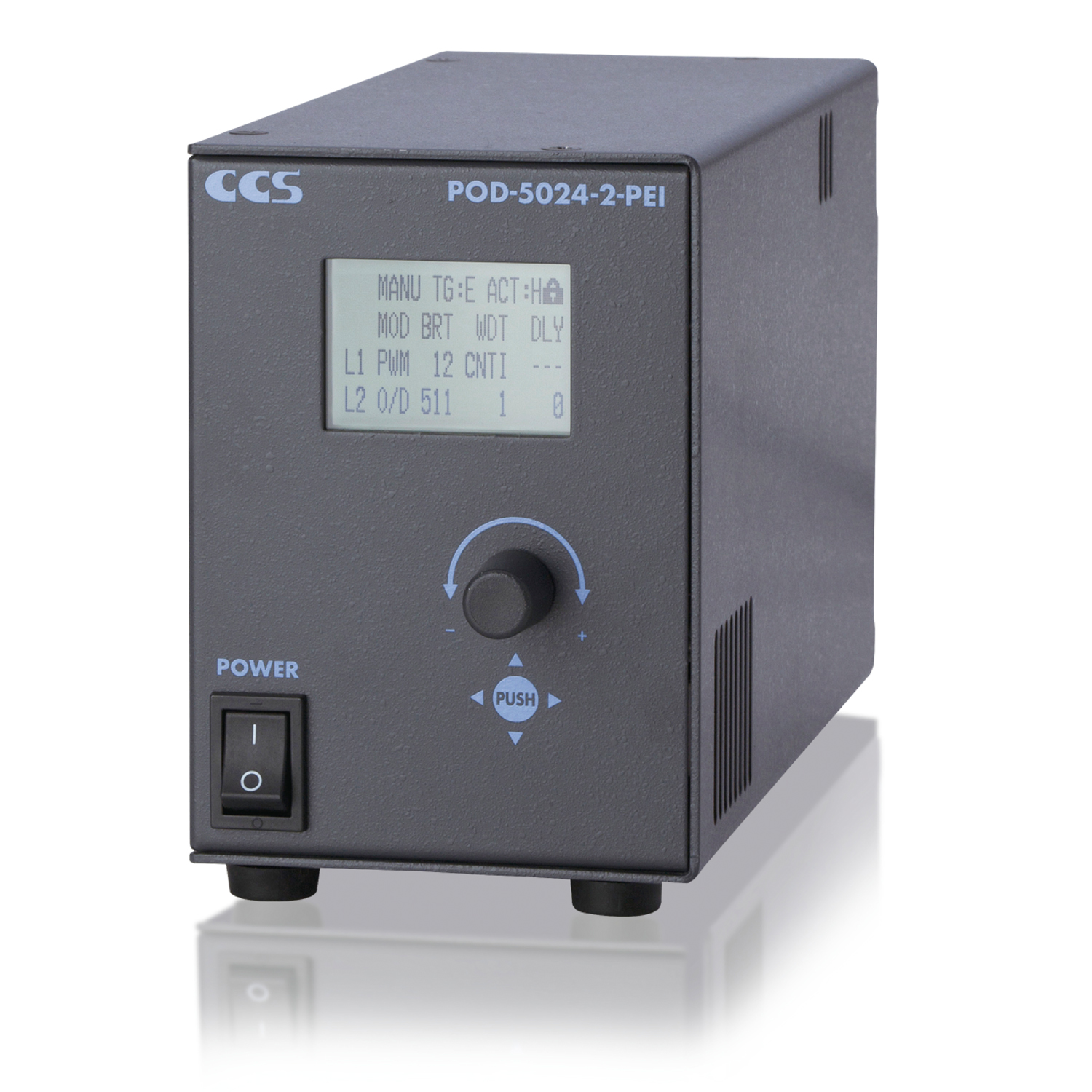
POD-5024-2-PEI

Strobe time
For manual control, Ethernet communications, and parallel communications
1~1,000μs(in steps of 1 μs)
2 channels with 2 connectors
Light connectors
- Two SM connectors (L1 and L2 channels)
A Specification Difference between POD-5024-2-PEI and POD-22024-4-PEI
In POD-22024-4-PEI (4-channel model), the lighting mode setting (Overdrive or PWM) is applied to all channels. Please note that the setting cannot be individually specified for each channel as in POD-5024-2-PEI (2-channel model).
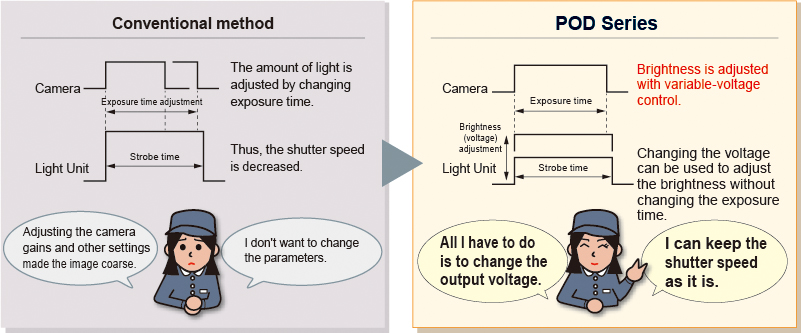
Using the POD Series
"I don't want to change the camera settings.
I want to adjust only the brightness of the Light Unit."
Switching the scene according to the inspection item.
A new function added to the 4-channel model for implementing varied lighting style
Trigger Link Function
You can make the Light Units on multiple channels turn ON (or OFF) with a single trigger signal that is input through one of the pins of the trigger input connector.
Simultaneous control of Light Units
installed in four directions

Individual control of multiple Light Units for
different inspections

Example connections
Refer to the “Instruction Guide” for details.
Example connections
of external trigger signal

Example connections
of external trigger signal
(Applying scenes)

Example connections
of external signal
(Parallel communications)
Example system configuration

Video
Watch the video below.
How to Check Lighting Connection Combinations
Make sure that the total input current of the connected Light Units is no more than the output current of the Control Unit.
Contact your sales representative for details.
Products
-
Machine Vision Applications
Ring
Low-angle Ring
Waterproof Ring
Bar (Area)
Low-angle Square
Flat
Flat Dome
Line Pattern
Dome
Coaxial
Cylinder
High Power Strobe
UV Lights [Ultraviolet Lighting] / Violet Light
IR Lights [Infrared Lighting] (under 1000nm)
IR Lights [Infrared Lighting] (over 1000nm)
Spot
Fiber Heads
Light Source Unit
Line (Convergent Lighting)
Line (Diffused Lighting)
Line (Oblique Angled Lighting)
Reference Light Source
Lights for Fringe Interference Inspection
Custom Order Product
Intensity Control Units [Light Units with Intensity Control Unit ]
Effilux Products
Basler Camera Light Series
- BCL Series (Bar Light)
- BCR Series (Ring Light)
- BCBL Series (Flat Light)
- BCF Series (Flood Light)
- BCL Series (Bar Light) Diffusion Plates
- BCR Series (Ring Light) Diffusion Plates
- BCF Series (Flood Light) Transparent Plate
- BCL Series (Bar Light) Light Polarizing Plates
- BCR Series (Ring Light) Polarizing Plates
- BCF Series (Flood Light) Polarizing Plates
- BCR Series (Ring Light) Light Adapter
- BCL Series (Bar Light) Light Bracket
- Basler Camera Light dedicated cable
-
Control Units
Digital Control Units
Strobe Unit
High Power Strobe Control Unit
PoE Enabled Controller
Controller with EtherNet/IP Interface
LED Light Controller
Control Units [for the HLV Series]
High-capacity Constant-current Control Units
High-capacity Analog Control Unit
Control Units [for CCS AItec]
-
Cables
Straight Cables
2-way Cables
4-way Cables
Robot Cables
2-way Robot Cables
4-way Robot Cables
Straight Cables [EL connector type]
2-way Cables [EL connector type]
Extension Cable [for PF Series]
Straight Cables for metal connector (7 pins)
Straight Cables for metal connector (37 pins)
Straight Cables for M12 connector
External Control Cables
Relay Connector
AC Power Cable
-
Options
Filters
Diffusion Plates
- Diffusion Plates [for Ring Lights]
- Diffusion Plates [for LDR-PF Series]
- Diffusion Plates [for LDR-PF-LA Series]
- Diffusion Plates [for Low-angle Ring Lights]
- Diffusion Plates [for Bar Lights]
- Diffusion Plates [for LDL-PF Series]
- Diffusion Plates [for HLDL3 Series]
- Diffusion Plates [for LB Series]
- Diffusion Plates [for Coaxial Lights]
- DF Series
- DF80 Series
Polarizing Plates
- Polarizing Plates [for Ring Lights]
- Polarizing Plates [for LDR-PF Series]
- Polarizing Plates [for Bar Lights]
- Polarizing Plates [for LDL-PF Series]
- Polarizing Plates [for HLDL3 Series]
- Polarizing Plates [for LB Series]
- Polarizing Plates [for Coaxial Lights]
- Polarizing Plates [for IR Series Infrared Lights (over 1000-nm type)]
- PL Series (FASTUS)
Light Control Films
Protective Plates
Adapter [for the CSR Series]
Lens Attachment Rings
Fixtures
Fixtures
Converter
Coaxial Units
Reflection Plate
Condenser lens
-
Lenses
Telecentric Lenses
Macro Lenses
-
Software Tools
Program for controllers
Version Upgrade for controllers
Application note for controllers
-
Agri-Bio Lighting
LED Light Units for Plant Research
ISL-150X150 Series Unit
ISL-150X150 series cables
-
Human Vision Inspection and Microscope Applications
LED Light Units for Microscopes
 Request Free Trial
 Request Quotation
 Inquiry Form
 Locations