
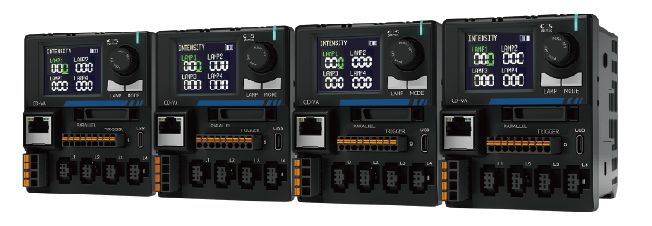
CD-VA Series
Supports 3 intensity control methods.
Up to 4 units can be connected via infrared communication and maximum 16-channel control is available.
Features
Features
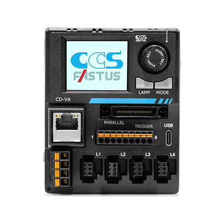
- Compact design with balanced operability and functionality
- Lighting output of 100 W with 2 channels and 200 W with 4 channels available (Max 50 W for each channel)
- Up to 4 units can be connected via infrared communication
- 3 intensity control methods can be set by channel
(PWM control, variable-voltage control, strobe overdrive) - Clear and visible display screen and intuitive operation
Supports 3 Intensity Control Methods
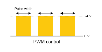
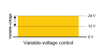
Choose the control method for each channel between general PWM (pulse width modulation), variable-voltage control suited to line scan camera inspections, and strobe overdrive allowing brighter lighting.
One control unit supports various types of inspections.
PWM control
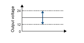
Variable-voltage control
Strobe overdrive
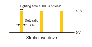
* Operates when lighting time is 1000 μs or less. When the lighting time is set in units of ms, the strobe overdrive does not operate.
Operation is at normal voltage (24 V).
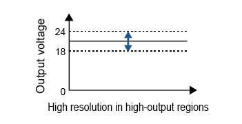
Variable-voltage control dimmer range
Dimmer range can be switched between 2 levels.
Select according to lighting characteristics or applications.
Depending on the characteristics of the connected light, the light may turn on at different dimming values. In some cases, it may turn ON even at a dimming value of 0.
Strobe overdrive
See the URL below for the combinations of LED lighting available when using strobe overdrive.
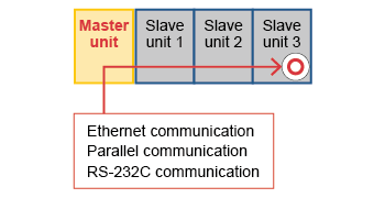
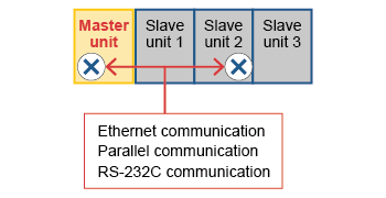
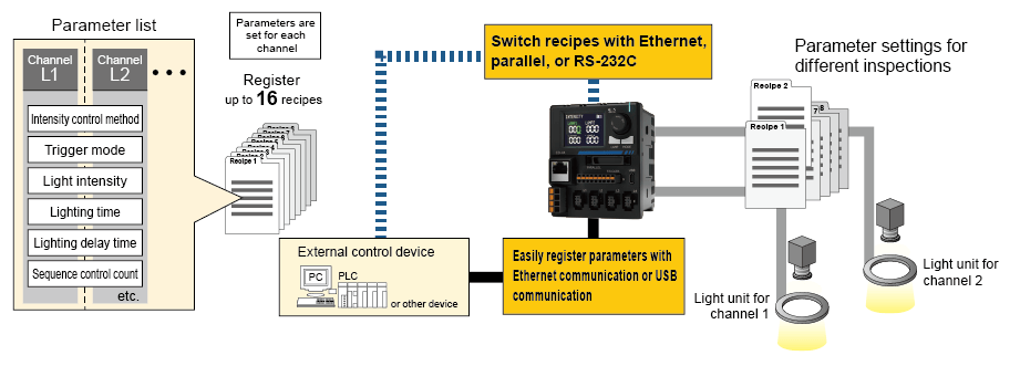
Connect Up to 4 Units
Maximum 16-channel control is available*
Up to 4 units can be connected to control via infrared communication.
For example, with four units of the 4-channel type connected, the lighting parameters can be set for up to 16 channels.
External control cables for each unit are unnecessary as the parent unit can control settings on the connected units.
By using the setting copy function, setting can be easily reflected to each channels, allowing for reduced workload.
Caution: For ON/OFF control via trigger input, individual connection to control unit and control is required.
* With 4 units of the 4-channel model connected
Control to expansion units
Only the main unit can control the connected expansion units.
Setting controls on an expansion unit does not apply the same changes to the main unit and the other expansion units.
When using CD-VA as a main unit, OPPX Series, FALUX sensing+ function is unavailable.
Features 2
Sequence Control
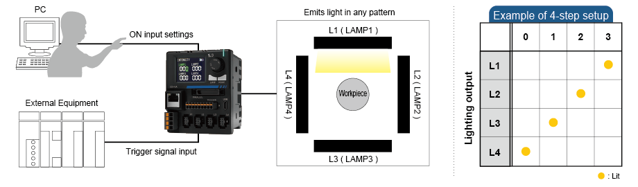
Emits light in any pattern
Program up to 16 steps of ON input for a pattern of light emission with desired intensity and emission time.
For example, when using 4-quadrant bar lights or segmented lights to illuminate from multiple directions,
the emission patterns for each channel can be stored and switched ON/OFF by trigger input.
Sequence control application examples
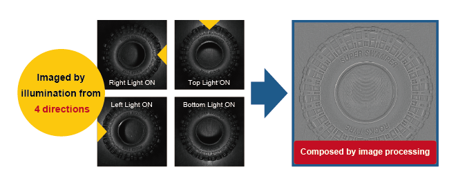
Photometric stereo imaging
The workpiece is illuminated and imaged from 4 directions.
It is possible to generate images that highlight only the unevenness or extract only the pattern by using the differences of each captured image.
Recipe Setting Function
Up to 16 lighting setting parameters can be saved
Parameter settings such as intensity values for each channel and other inspection-specific parameter settings can be
registered in advance,
allowing for easy setting changes simply by recalling recipes.
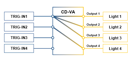
Trigger Input Assignment Function
Trigger Input Assignment Function
Control ON/OFF of multiple lights with 1 trigger input. Change assignments even after wiring.
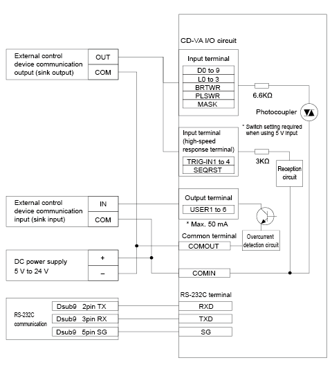
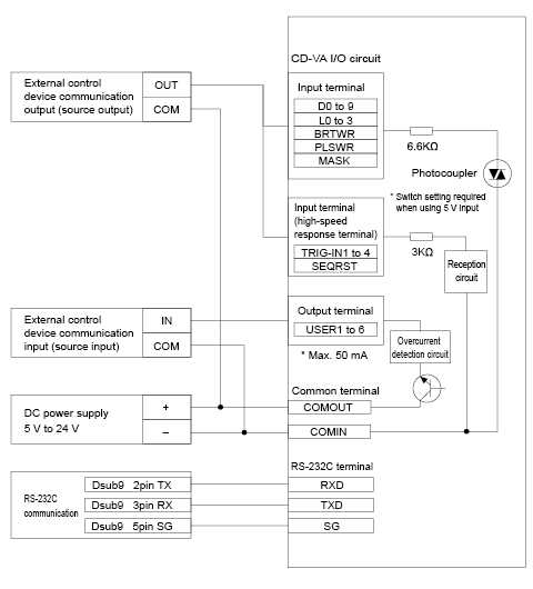
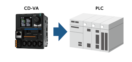
Communication function
External Signal Connection Example
(Both NPN and PNP connections are supported and logic switching is possible.)
NPN connection (sink connection)
PNP connection (source connection)
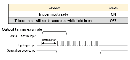
Enhanced Status Confirmation Functions
Status of the control unit and light (errors, ON/OFF, etc.) can be confirmed using the output* function.
* There are two output systems: parallel and trigger pin.
Usage example: Trigger input ready status confirmation
Output ON: each channel can accept a trigger input. Output OFF: When the lights are on or when trigger acceptance is disabled in strobe mode.
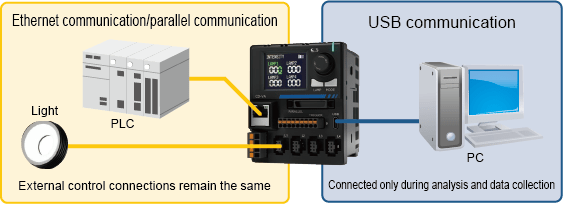
USB connector (Type-C) for data communication
USB connector (Type-C) for data communication with a PC even while connected to external control devices.
USB connection image
Check settings and verify operation using the CD-VA dedicated app (utility software).
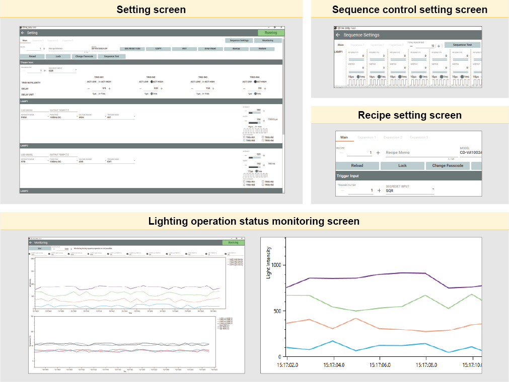
Application
Setting Application CD-VA Dedicated App (Utility Software)
A dedicated app to easily set lighting parameters
Set each channel's dimming value and ON/OFF control, as well as sequence control, recipe setting,
ON/OFF input assignment, etc. The app also monitors operation status.
- Please check "System Requirements for Product Applications" for the system requirements of this program.
- The dedicated application can be downloaded from the Product Lineup.
Options / Software Tools
Option
Trigger cable(Model name:EXCB2-FER08-22-3-9CL)

* This product comes with 9 wires/set.
External control cable(Model name:EXCB2-FX32-9F-3, EXCB2-FX32-3)


Ferrite core (Model name: OP-NFT-13S)
Recommended installation location: Lighting output cable termination of CD-VA
Contact your local sales office for details.
Software Tools
Applicable Software Versions
The following CD-VA software versions can be upgraded to the new version.
Products
-
Machine Vision Applications
Ring
Low-angle Ring
Waterproof Ring
Bar (Area)
Low-angle Square
Flat
Flat Dome
Line Pattern
Dome
Coaxial
Cylinder
High Power Strobe
UV Lights [Ultraviolet Lighting] / Violet Light
IR Lights [Infrared Lighting] (under 1000nm)
IR Lights [Infrared Lighting] (over 1000nm)
Spot
Fiber Heads
Light Source Unit
Line (Convergent Lighting)
Line (Diffused Lighting)
Line (Oblique Angled Lighting)
Lights for Fringe Interference Inspection
Reference Light Source
Custom Order Product
Intensity Control Units [Light Units with Intensity Control Unit ]
Effilux Products
Basler Camera Light Series
- BCL Series (Bar Light)
- BCR Series (Ring Light)
- BCBL Series (Flat Light)
- BCF Series (Flood Light)
- BCL Series (Bar Light) Diffusion Plates
- BCR Series (Ring Light) Diffusion Plates
- BCF Series (Flood Light) Transparent Plate
- BCL Series (Bar Light) Light Polarizing Plates
- BCR Series (Ring Light) Polarizing Plates
- BCF Series (Flood Light) Polarizing Plates
- BCR Series (Ring Light) Light Adapter
- BCL Series (Bar Light) Light Bracket
- Basler Camera Light dedicated cable
-
Control Units
Digital Control Units
Strobe Unit
High Power Strobe Control Unit
PoE Enabled Controller
Controller with EtherNet/IP Interface
LED Light Controller
Control Units [for the HLV Series]
High-capacity Constant-current Control Units
High-capacity Analog Control Unit
Other Control Units
-
Cables
Straight Cables
2-way Cables
4-way Cables
Robot Cables
2-way Robot Cables
4-way Robot Cables
Straight Cables [EL connector type]
2-way Cables [EL connector type]
Extension Cable [for PF Series]
Straight Cables for metal connector (7 pins)
Straight Cables for metal connector (37 pins)
Straight Cables for M12 connector
External Control Cables
Relay Connector
AC Power Cable
-
Options
Filters
Diffusion Plates
- Diffusion Plates [for Ring Lights]
- Diffusion Plates [for LDR-PF Series]
- Diffusion Plates [for LDR-PF-LA Series]
- Diffusion Plates [for Low-angle Ring Lights]
- Diffusion Plates [for Bar Lights]
- Diffusion Plates [for LDL-PF Series]
- Diffusion Plates [for HLDL3 Series]
- Diffusion Plates [for LB Series]
- Diffusion Plates [for Coaxial Lights]
- DF Series
- DF80 Series
Polarizing Plates
- Polarizing Plates [for Ring Lights]
- Polarizing Plates [for LDR-PF Series]
- Polarizing Plates [for Bar Lights]
- Polarizing Plates [for LDL-PF Series]
- Polarizing Plates [for HLDL3 Series]
- Polarizing Plates [for LB Series]
- Polarizing Plates [for Coaxial Lights]
- Polarizing Plates [for IR Series Infrared Lights (over 1000-nm type)]
- PL Series (FASTUS)
Light Control Films
Protective Plates
Adapter [for the CSR Series]
Lens Attachment Rings
Fixtures
Fixtures
Converter
Coaxial Units
Reflection Plate
Condenser lens
-
Lenses
Telecentric Lenses
Macro Lenses
-
Software Tools
Program for controllers
Version Upgrade for controllers
Application note for controllers
-
Agri-Bio Lighting
LED Light Units for Plant Research
ISL-150X150 Series Unit
ISL-150X150 series cables
-
Human Vision Inspection and Microscope Applications
LED Light Units for Microscopes
 Request Free Trial
 Request Quotation
 Inquiry Form
 Locations