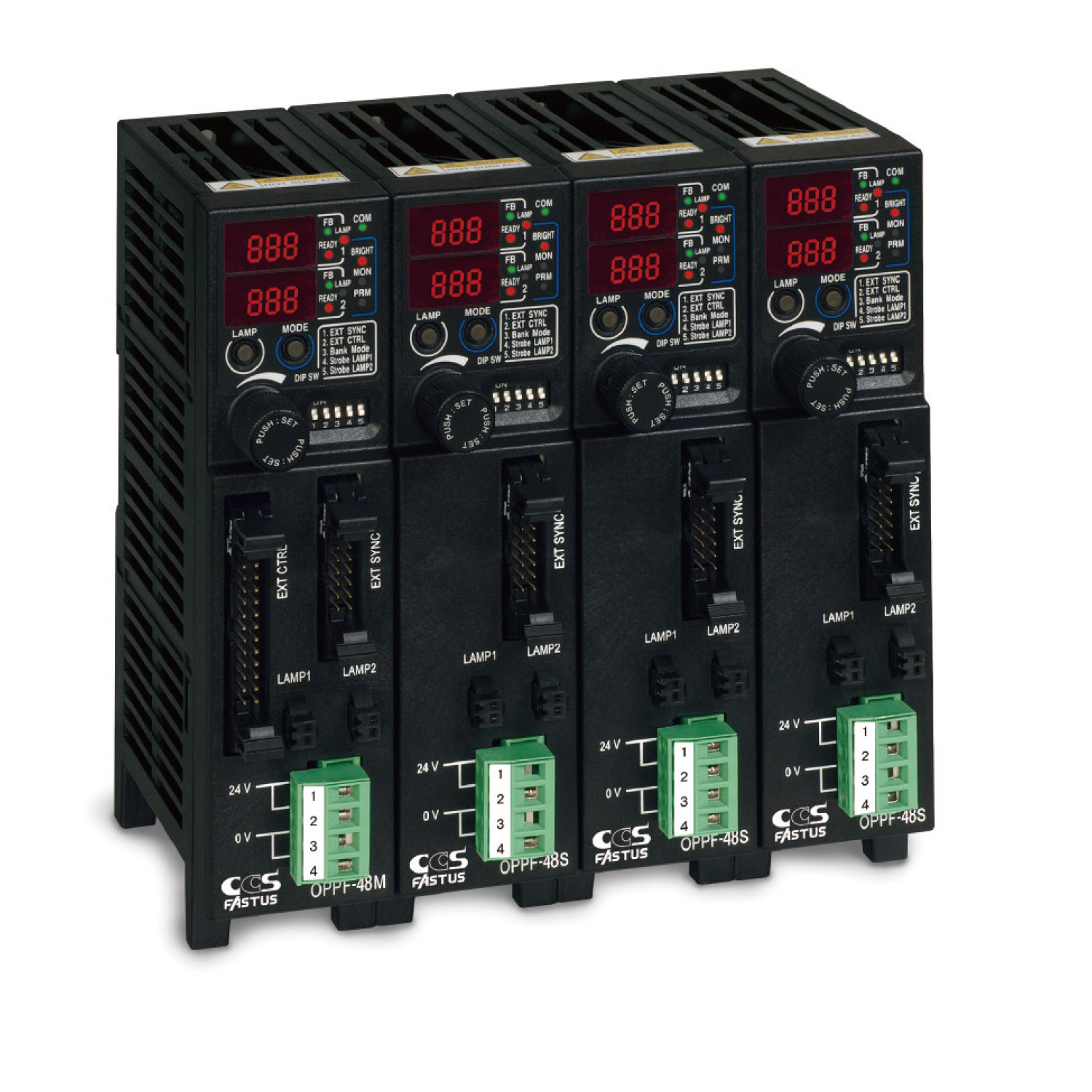
OPPF Series
[Not available in Japan]Increased-capacity controller with built-in sensing function
Features
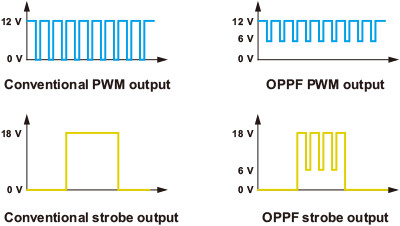
Support for both PWM light intensity control and strobe illumination

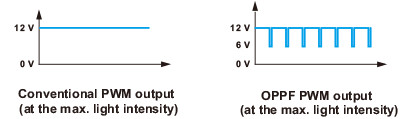
High-brightness settings with 1,000 intensity steps are possible with a PWM frequency of 100 kHz.
Lighting with up to 48 W total for 2 LAMP outputs can be connected. (Max. 30 W per channel)

High-brightness settings with 1,000 intensity steps are possible.
In addition, 1,000 steps with light emission widths from 10 μs to 9.99 ms at 10 μs intervals can be set.
The minimum settable light emission width is 1 μs (light emission width: 10 μs, intensity setting: 10%).
Light emission widths of 1 ms or less offer 3 times the brightness with 18 V overdrive output.
Lighting with up to 24 W for each LAMP output can be connected.
-
- Approx. 6 V will be applied to drive the internal circuit of the lighting while it is not lit. The LEDs will not illuminate in this case.
-
- The illumination state is not the same as that of with DC current even at 100% intensity illumination because the communication signals are superimposed.
 Connect lighting equipped with “FALUX sensing” to monitor brightness and temperature and to control feedback
Monitoring function
- Accurately measure brightness not only during continuous illumination but also with ON/OFF control and strobe illumination.
- This makes it possible to output an alarm when brightness decreases to a predetermined value.
- Absolute brightness monitoring makes it possible to adjust for lighting instrumental errors.
- In addition to brightness, measurement of internal temperatures is also possible.
Feedback (FB) control
- FB control eliminates not only variations over long periods but also the need to perform periodic adjustments to the light intensity setting. By comparing the measured emission brightness with the lighting’s recorded reference brightness, FB control fine tunes the output voltage to match the standard brightness.
- FB control also allows for compensation of reductions in brightness due to a voltage drop in the extension cable.
- A signal is output as a feedback error when the upper or lower output voltage adjustment limit is reached.
- Output voltage
PWM mode: 11 to 18 VDC
Strobe mode: 16 to 22 VDC - FB accuracy: ±1.5% or less (typ.)

The OPPF Series not only provides power for lighting from two conventional main line cables but also superimposes signals for communication with lighting. This allows for conventional use even with lighting that is not equipped with “FALUX sensing”.
External light intensity control
Using RS232 communication and external parallel input, centralized intensity control of all lamps is possible from the master device. Intensity control is possible by 0 to 5?V analog input to the individual lamps of each unit.
Multi-channel support
- With 2 channels per unit, support for up to 8 channels is possible by linking (DIN mounting) 3 master and slave devices.
- Communication between units is connector-less and uses infrared.
- A setting copy function allows settings to be batch copied to all channels.
- Connecting a single slave device or just a slave device is possible.

Bank registration of light intensity values
- Pre-set intensity values can be configured and saved in the main unit, allowing for switching between intensity values with fewer inputs.
- Up to 16 banks can be registered for each LAMP.
- In addition to settings from the operation panel, switching is also possible through external parallel input and RS232 communication.
Surprisingly low price for provided functionality
- Progressively expanding functionality to meet the diverse needs of customers.
- Even with these functions, prices are kept lower than general-purpose controllers.
- Lowest price range available for strobe-equipped devices.
Part Names

I/O Function List
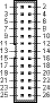
Master device MIL 26-pin connector ? EXT CTRL
| Pin No. | Name | Input/output | Signal name | Description |
|---|---|---|---|---|
| 1 | D0 | Input | Intensity bit 0 / Bank selection 0 (LSB) | For external light intensity control (DSW2-ON) not in bank mode (DSW3-OFF), these terminals correspond to lower bits 0 to 3 for setting the light intensity value through external parallel input. For external light intensity control (DSW2-ON) in bank mode (DSW3-ON), these terminals are used to specify the bank number. |
| 2 | D1 | Input | Intensity bit 1 / Bank selection 1 | |
| 3 | D2 | Input | Intensity bit 2 / Bank selection 2 | |
| 4 | D3 | Input | Intensity bit 3 / Bank selection 3 | |
| 5 | D4 | Input | Intensity bit 4 | Correspond to upper bits 4 to 9 when switching the light intensity value through external parallel input. Values are specified in binary. Available for light intensity control (DSW2-ON) not in bank mode (DSW3-OFF). |
| 6 | D5 | Input | Intensity bit 5 | |
| 7 | D6 | Input | Intensity bit 6 | |
| 8 | D7 | Input | Intensity bit 7 | |
| 9 | D8 | Input | Intensity bit 8 | |
| 10 | D9 | Input | Intensity bit 9 | |
| 11 | L0 | Input | LAMP select 0 | Specifies the station number of the target lamp with external intensity control or when switching banks. With a master device, LAMP1 is selected when L2, L1, and L0 = OFF, and LAMP2 is selected when L2 and L1 = OFF while L0 = ON. |
| 12 | L1 | Input | LAMP select 1 | |
| 13 | L2 | Input | LAMP select 2 | |
| 14 | WR | Input | Light intensity writing | Turning ON this input allows light intensity values to be written. If bank numbers are specified, this function is not necessary. |
| 15 | COMINA | - | Input COM | This is the common terminal for input. The corresponding input can be turned ON by applying 5 to 24 V between each input and this common terminal. (No polarity) |
| 16 | COMOUTA | - | Output COM | This is the common terminal for output. When output is ON, the current flows from the output terminal to this common terminal. (Opposite direction for PNP types) |
| 17 | ERR | Output | Error output (FB, overcurrent) | This output turns ON when a feedback error or monitor brightness alarm occurs, when the internal temperature is abnormal, or when the overcurrent protection circuit of the lighting is operating. Error output also turns on if an error is output for any connected slave device. (A delay of up to 250 ms will occur before a slave device error status is reflected.) |
| 18 to 23 | - | - | - | - |
| 24 | TXD | Output | Serial TXD | This is the transmission output for RS232. |
| 25 | RXD | Input | Serial RXD | This is the reception input for RS232. |
| 26 | SG | - | Serial GND | This is the common terminal for RS232. |
Master/slave device MIL 14-pin connector ? EXT SYNC
| Pin No. | Name | Input/output | Signal name | Description |
|---|---|---|---|---|
| 1 | SYNC1 | Input | LAMP1 ON/OFF control input | With external ON/OFF control (DWS1=ON), the polarity can be switched from  in the PRM settings while this input is ON. LAMP1 becomes illuminated. In strobe mode (DSW4=ON), LAMP1 illuminates on the leading edge of this input. in the PRM settings while this input is ON. LAMP1 becomes illuminated. In strobe mode (DSW4=ON), LAMP1 illuminates on the leading edge of this input. |
| 2 | SYNC2 | Input | LAMP2 ON/OFF control input | With external ON/OFF control (DWS1=ON), the polarity can be switched from in the PRM settings while this input is ON. LAMP2 becomes illuminated. In strobe mode (DSW5=ON), LAMP2 illuminates on the leading edge of this input. |
| 3 | COMINB | - | Input COM | This is the common terminal for input. The corresponding input can be turned ON by applying 5 to 24 V between this common terminal and either ON/OFF control input or analog intensity control switching input. (Nopolarity) |
| 4 | COMOUTB | - | Output COM | This is the common terminal for output. When each output is ON, the current flows from the output terminal to this common terminal. (Opposite direction for PNP types) |
| 5 | OVC | Output | Overcurrent error | Overcurrent error output turns ON if an overcurrent occurs for either LAMP1 or LAMP2 lighting. |
| 6 | FBERR1 | Output | LAMP1 feedback error | This output turns ON when a LAMP1 feedback error or monitor brightness alarm occurs. |
| 7 | LON1 | Output | LAMP1 ON output | This output turns ON while LAMP1 is outputting. |
| 8 | FBERR2 | Output | LAMP2 feedback error | This output turns ON when a LAMP2 feedback error or monitor brightness alarm occurs. |
| 9 | LON2 | Output | LAMP2 ON output | This output turns ON while LAMP2 is outputting. |
| 10 | ANALOG | Input | Analog intensity control switching input |
Turning ON this input allows light intensity control to be performed using analog input AIN1 and AIN2 voltage. Only turning ON/OFF for both LAMP1 and LAMP2 is allowed. Applying 5 to 24 V between this terminal and COMINB will turn ON analog intensity control. Also, the  item in the PRM settings can specify force analog intensity control to be enabled. item in the PRM settings can specify force analog intensity control to be enabled. |
| 11 | AIN1 | Input | LAMP1 analog input | This is the analog input for LAMP1. At 0 to 5 V, the corresponding light intensity value will be between 0 and 999. |
| 12 | 5 V | Output | Auxiliary 5 V output | This is the 5 V output that can be used for analog input. |
| 13 | AIN2 | Input | LAMP2 analog input | This is the analog input for LAMP2. At 0 to 5 V, the corresponding light intensity value will be between 0 and 999. |
| 14 | ACOM | - | Analog common | This is the common terminal for analog input. |
Installation
Installation examples
Rear DIN mounting or screw mounting is possible.
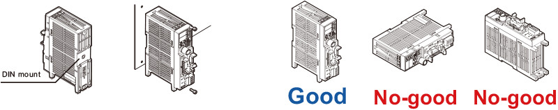
Always use upright to allow for heat dissipation. Do not use in any position other than the upright.
Cable connectivity
Master/slave device: 24 VDC input (power source)
Applicable wiring: 0.2 to 2.1 mm2, 24 to 14 AWG
Insulation strip length: 7 mm
Upper 2-pole: 24 VDC, Lower 2-pole: 0 V
Note: Use open terminals to pass power between units with 1 pole per wire.
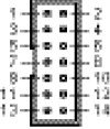
Master device: MIL 26-pin connector (EXT CTRL)
Master/slave device: MIL 14-pin connector (EXT SYNC)
[Optional cables]
MIL socket connector harness (type with one side trimmed)
28 AWG twisted-pair double-shielded cable

Note: Please use shielded cables in environments susceptible to noise.
Required 24 VDC power supply capacity to handle power consumption of lighting
Based on the total power consumption of the LED lighting to be connected, select a 24 VDC power source that offers more than the required capacity.
Note: When using in conjunction with other equipment, the characteristics of the other equipment will affect the power supply, so be sure to choose a power supply that has a sufficient margin (about twice as much) as that shown in the graph.
*Evaluation power source: IDEC PS5R-SF24 (120 W), PS5R-SG24 (240 W)

Connection to External Device
Standard type


Products
-
Machine Vision Applications
Ring
Square
Bar (Area)
Flat
Dome
Cylinder
Box
Spot
Line (Convergent Lighting)
Line (Diffused Lighting)
Line (Oblique Angled Lighting)
UV Lights [Ultraviolet Lighting] / Violet Light
IR Lights [Infrared Lighting] (under 1000nm)
Custom Order Product
Intensity Control Units [Light Units with Intensity Control Unit ]
OLED(CCS-LT)
Effilux Products
Basler Camera Light Series
- BCL Series (Bar Light)
- BCR Series (Ring Light)
- BCBL Series (Flat Light)
- BCF Series (Flood Light)
- BCL Series (Bar Light) Diffusion Plates
- BCR Series (Ring Light) Diffusion Plates
- BCF Series (Flood Light) Transparent Plate
- BCL Series (Bar Light) Light Polarizing Plates
- BCR Series (Ring Light) Polarizing Plates
- BCF Series (Flood Light) Polarizing Plates
- BCR Series (Ring Light) Light Adapter
- BCL Series (Bar Light) Light Bracket
- Basler Camera Light dedicated cable
IR Lights [Infrared Lighting] (over 1000nm)
Reference Light Source
Lights for Fringe Interference Inspection
-
Agri-Bio Lighting
LED Light Units for Plant Research
ISL-150X150 Series Unit
ISL-150X150 series cables
-
Human Vision Inspection and Microscope Applications
LED Light Units for Microscopes
-
Power Supplies
High Power Strobe Control Unit
Digital Control Units
Analog Control Units
LED Light Controller
Control Units [for the HLV Series]
Strobe Unit
High-capacity Analog Control Unit
High-capacity Constant-current Control Units
Controller with EtherNet/IP Interface
PoE Enabled Controller
Control Units [for CCS AItec]
Program for controllers
-
Cables
Extension Cable [for PF Series]
Straight Cables
2-way Cables [EL connector type]
4-way Cables
Robot Cables
Straight Cables [EL connector type]
2-way Cables [EL connector type]
Straight Cables for metal connector (7 pins)
Straight Cables for metal connector (37 pins)
Straight Cables for M12 connector
External Control Cables
Relay Connector
-
Options
Filters
Polarizing Plates
- Polarizing Plates [for IR Series Infrared Lights (over 1000-nm type)]
- Polarizing Plates [for HLDL3 Series]
- Polarizing Plates [for LB Series]
- Polarizing Plates [for LDR-PF Series]
- Polarizing Plates [for LDL-PF Series]
- Polarizing Plates [for Ring Lights]
- Polarizing Plates [for Bar Lights]
- Polarizing Plates [for Coaxial Lights]
- PL Series (FASTUS)
Diffusion Plates
- Diffusion Plates [for HLDL3 Series]
- Diffusion Plates [for LB Series]
- Diffusion Plates [for LDR-PF Series]
- Diffusion Plates [for LDL-PF Series]
- Diffusion Plates [for Ring Lights]
- Diffusion Plates [for Low-angle Ring Lights]
- Diffusion Plates [for Bar Lights]
- Diffusion Plates [for Coaxial Lights]
- DF80 Series
- DF Series
- Diffusion Plates [for LDR-PF-LA Series]
- DF-ISL-165X165 Series
Light Control Films
Adapter [for the CSR Series]
Lens Attachment Rings
Fixtures
Converter
Protective Plates
Coaxial Units
Fixtures
Reflection Plate
Condenser lens
-
Lenses
Telecentric Lenses
Macro Lenses
 Request Free Trial
 Request Quotation
 Inquiry Form
 Locations