Q&A
Control Units
PD2
![]() Is there a table that compares the PD2-3024 Series and PD3-3024 Series units?
Is there a table that compares the PD2-3024 Series and PD3-3024 Series units?
![]()
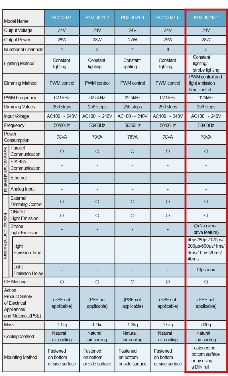
A table comparing the PD2-3024 Series and PD3-3024 Series units is given below.
(Common specifications for PI, SI, and EI.)
QA No. 12-0001
![]()
Since the frequencies are different and the FET gate voltages are different, they are not completely compatible with each other.
Additionally, linearity is roughly equivalent for both series units.
QA No. 11-0144
![]() Are there any noise related issues for the PD3 Series?
Are there any noise related issues for the PD3 Series?
![]()
Since it depends on the usage environment, although it is hard to say for sure, since the units for this series perform external control using photo coupler input and they are equipped with noise suppressing countermeasures based on the techniques we have refined over the years, it is fair to say that they are more resistant than the PD2 Series.
QA No. 11-0143
![]() When installing the PD2 and PSB units, is it possible to stack them on top of each other?
When installing the PD2 and PSB units, is it possible to stack them on top of each other?
![]()
They are not designed to a specification that allows for stacking on top of each other.
Please do not use them in a stacked arrangement.
QA No. 11-0102
![]() What are the differences between the PSB and PD2 units?
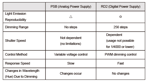
What are the differences between the PSB and PD2 units?
![]()
QA No. 11-0101
![]()
It is possible to use it in this way.
If the signal ground line and the ground line used by the customer is connected with each other, it is possible to extract the signal from the over-current protection pin.
When doing so, please leave all other pins unconnected and open.
QA No. 11-0099
![]()
Please use a ceramic capacitor.
(Please use it in an environment that is free from the effects of noise.)
QA No. 11-0098
![]()
There is no problem if the unit is used with the attachment hole on its left side facing down.
If the unit is turned with the left side facing up, the circuit board will be on top, resulting in poorer heat dissipation due to the positioning of the switching Control Unit, etc., underneath it, and there is a risk that it will not be able to supply the specified output.
QA No. 11-0097
![]()
| PD | Channel 1, 2...4.7kOhm |
|---|---|
| PD | Channel 4, 8...1.5kOhm |
| PD2 | Channel 1, 2...4.7kOhm |
| PD2 | Channel 4, 8...2.2kOhm |
QA No. 11-0096
![]()
Since it is a negative logic output, when the signal is "0," the voltage level will be "high."
"ExtMode" switching can only be performed using the lighting ON/OFF signal.
QA No. 11-0095
![]()
Internal and external switching setting will apply to all channels.
QA No. 11-0094
![]()
They are internally connected. Either one can be used without any issues.
QA No. 11-0093
![]()
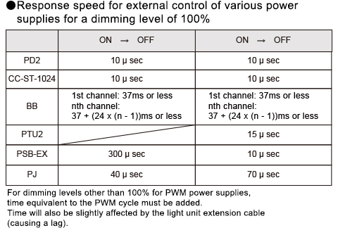
The ON/OFF response time is approximately a minimum of 10μs.
(This may vary for custom order power supplies.)
QA No. 11-0092
![]()
Since the unit is designed with fastening screw holes, please be careful to mount it properly.
As there are restrictions we ask that you inquire further with our sales representatives.
QA No. 11-0091
![]()
We apologize as we are unable to provide you with a AC 200V cable.
We ask that you prepare one that matches your own usage environment.
QA No. 11-0090
![]()
The fastening screw holes are located on the bottom and side surface. However, only some products for this series feature screw holes on the side surface.
Additionally, the screw holes on the bottom surface are in a location where they are hidden from view by the rubber feet.
QA No. 11-0089
![]() The adjustment knob for our PD2 Series unit is broken. Can we purchase another one?
The adjustment knob for our PD2 Series unit is broken. Can we purchase another one?
![]()
We offer repairs for such cases.
Please inquire further with our sales representatives.
QA No. 11-0086
![]()
After adjusting the camera shutter, please input an ON/OFF trigger signal.
Please note, however, that it is not possible to completely synchronize camera and lighting.
QA No. 11-0085
![]()
This type of usage is not possible.
QA No. 11-0084
![]()
The maximum allowable voltage is 5.5V.
QA No. 11-0083
![]()
There is no correlation.
QA No. 11-0052
![]()
There is no conversion cable.
QA No. 11-0050
![]()
The total output power, is the sum total of power being output at the same time on channel 1 and channel 2, and it can reach a maximum of 28W
(maximum power for each single channel also amounts to 28W).
QA No. 11-0036