Theory of Light and Color
35. Tips for Using Illuminance Meters
When measuring the "brightness" of light, we often reach for tools like illuminance or luminance meters. These light measurement devices make it easy for anyone to get quick readings by simply pointing the sensor at the light source, pressing a button, and reading the value on the display screen. This simplicity makes them popular for quick and easy measurements in various settings. For accuracy, each device's manual will include information on measurement precision, often referencing standards like JIS (Japan Industrial Standards). With digital readouts that give precise values, most users likely assume they're getting perfectly accurate measurements. However, as we'll see, more factors can affect measurement reliability.
(1) Measurement Errors with Light Meters
When discussing measurement accuracy, it's important to remember that it results from a combination of factors. It's essential to understand these factors and apply them correctly, depending on the purpose and conditions of use. Although displayed measurements may appear accurate, different measurement methods can yield variable results. Yet, once a reading is obtained, there's a risk it may be considered absolute—sometimes with undue confidence.
The primary factors affecting the accuracy of light meter measurements fall into two categories: those caused by the device's hardware and those caused by the user's handling.
There are various types of light meters, designed to measure quantities like luminous flux, illuminance, and luminance, or radiant quantities like radiant flux, irradiance, and radiance. Hardware-related errors include spectral errors ≪1≫ and angular response errors, which occur when the device's optical system isn't fully aligned with the defined quantity. Other common issues, not limited to light meters, involve the linearity and stability of detection circuits, environmental factors (like temperature and humidity), and other usage conditions.
Hardware-related errors are largely determined by the device's design and model, as these factors are set once the device is selected. However, user-related errors are influenced significantly by their understanding of the light source and attention to measurement techniques.
This section will focus on the potential errors caused by user handling, specifically with handheld (filter-type) illuminance meters.
(2) Oblique Incident Light on the Photoreceptor
Illuminance refers to the luminous flux per unit area on a target plane. For luminous flux entering at an angle θ, it must be weighted by cos θ (refer to Chapter 8). Illuminance meters generally have a cosine response characteristic for oblique incident light. This means they measure light from both straight ahead and oblique angles, applying a cos θ weighting for angled light. ≪2≫
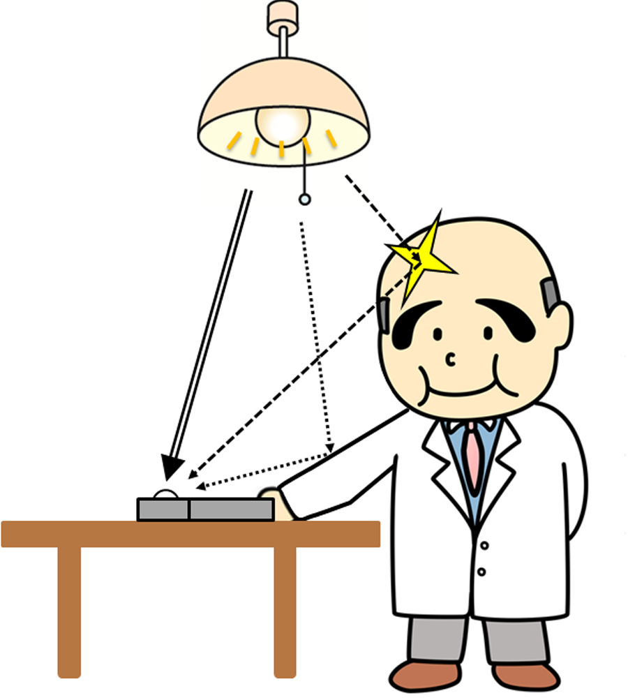
Let's consider measuring the illuminance on a desk from ceiling lighting. Assume there's only one ceiling light source and no window light. The desk's illuminance is mostly from direct ceiling light, plus some reflected light from walls and furniture.
When taking a measurement, you would place the illuminance meter on the desk and then measure. However, the person operating the meter can interfere with the reading. Their body or clothes may reflect light onto the sensor, or they might block reflections from walls. This can lead to measurement errors.
To minimize this, the operator should take measures to avoid reflecting light onto the sensor or blocking wall reflections. Additionally, it's preferable to wear dark clothing with low reflectance, rather than white or light-colored clothing with higher reflectance. For more accurate measurements, some illuminance meters offer remote measurement cables as accessories, allowing for better measurement conditions.
(3) Illuminance Distribution within the Sensor Area
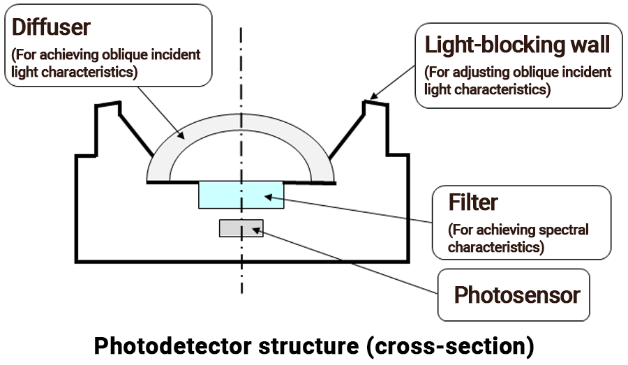
When using an illuminance meter, we assume the light distribution across the receiving area is uniform. In filter-type illuminance meters, sensitivity varies greatly depending on the position within the receiving area. This is because many meters use a hemispherical diffuser over the photosensor to achieve the cosine response for angled light. As a result, the path light takes to reach the sensor differs greatly depending on where it enters. If a narrow beam of light smaller than the receiving area enters the sensor, the displayed value can change significantly based on where it hits. This is easy to confirm by moving such a beam across the sensor.
Illuminance meters are calibrated and guaranteed to perform under conditions where light evenly covers the entire receiving area. Some people try to "correct" measurements of narrow beams by adjusting the reading based on the ratio of the beam's cross-section to the sensor area. But this actually makes the measurement worse, not better.
If you need to measure illuminance in an area smaller than the sensor's receiving area (such as spot lights), it's recommended to use a luminance meter with a standard reflector plate instead. (More details on this method will be covered in the next chapter.)
(4) Measurement Distance to the Light Source
When using an illuminance meter, measurements are generally taken at about 1 m or more from the light source, and measurement errors due to distance are usually minimal. However, there are cases where measurements are conducted very close to the light source (e.g., within 10 cm or closer). In such cases, the closer the distance, the greater the measurement error.
The theory behind illuminance meter calibration is based on the inverse square law of illuminance. This law states that for a point light source, the illuminance is inversely proportional to the square of the distance from the source.
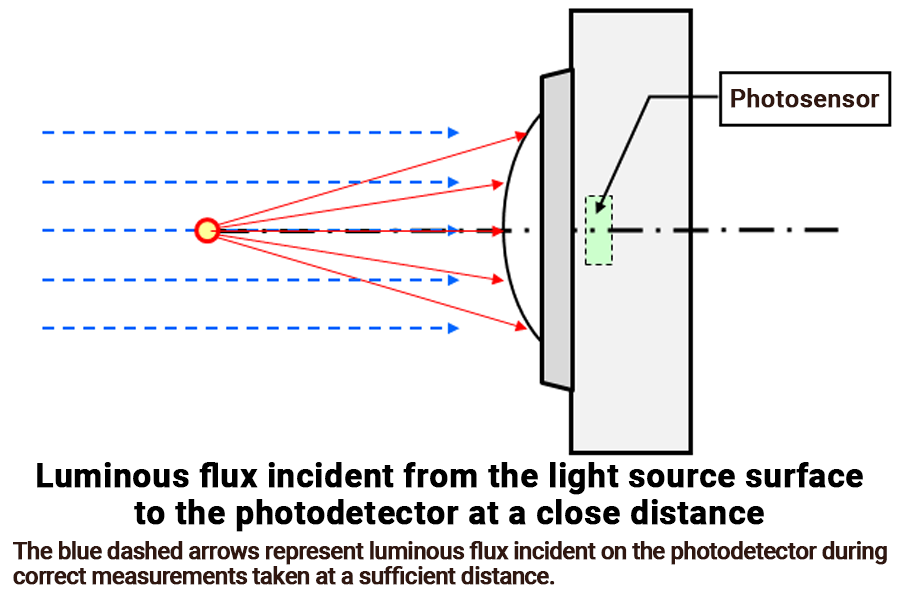
The illuminance meter is positioned in a darkroom on a photometric bench with a reference light source for calibration. After the light stabilizes, it's calibrated at a specified distance (usually around 1.5–2 m) to ensure accurate readings under these conditions. ≪3≫ At this calibration distance, the light source can be considered a "diffuse point source," and the light entering the sensor area is nearly parallel, entering perpendicularly and uniformly distributed across the sensor area.
The sensing area of an illuminance meter is not a point but has a certain area. As the distance to the light source decreases or the receiving area diameter increases, deviations from calibration conditions (parallel light incidence, uniform illuminance) become larger, leading to measurement errors. For diffuse light sources, a distance of about 10 times the sensor area diameter is generally sufficient to minimize errors. A longer distance is required for highly directional sources to achieve similar accuracy.
Moreover, real light sources are not points. A distance of about 10 times the light source diameter is usually enough to treat it as a point source with less than 1% error for diffuse sources. Directional light sources may need longer distances to achieve similar error levels.
Ultimately, the accuracy of illuminance measurements depends on keeping deviations from the theoretical inverse square law as minimal as possible. Specifically, the distance between the light source and the illuminance meter should be significantly larger relative to both the sensor area and source size.
In real measurement environments, light sources may vary widely in size, such as fluorescent lights or sunlight entering through large windows. There are cases when it is necessary to accurately measure illuminance from large-area sources that can't be considered point sources at practical distances.
These large-area sources can be thought of as aggregations of smaller elements, each acting as a point source at a sufficient distance. The light entering the sensor area from each of these elements is mostly parallel, creating uniform illuminance across the sensor. Thus, except at very close distances, large sources do not generally cause major measurement issues.
However, for precise measurements, such as determining LED intensity, careful attention should be given to both the distance criteria for the illuminance meter and the distance reference point of the light source (LED), as discussed in detail later. ≪4≫
(5) Distance Reference Position in Illuminance Meters
When we refer to the "distance" between a light source and an illuminance meter, where exactly do we measure from and to?
For a point source, the reference point is clear—it's the position of the light source. However, for area light sources, we use an average position, which can be vague. While this ambiguity usually doesn't cause significant issues during standard illuminance measurements, it can become a source of error in precise, close-range measurements.
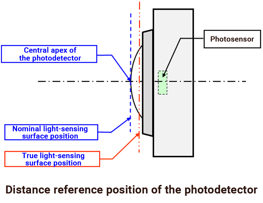
For filter-type illuminance meters, the nominal reference point is usually the top of the hemispherical diffuser. The distance to the light source is usually considered relative to this nominal point, which is sufficient for general measurements at sufficient distances.
However, the structure of the photodetector means that light enters the sensor from various points on the diffuser. Therefore, using the apex of the diffuser as the distance reference point does not fully represent all incoming light. The true light-sensing surface is better understood as the effective average position for all incoming light to accurately follow the inverse square law for illuminance. The actual effective receiving position is slightly behind the diffuser top (about a few millimeters). ≪5≫
When the light source is sufficiently far away (e.g., 1 m or more), the difference between nominal and true positions is negligible. However, at shorter distances, this discrepancy can introduce significant errors. For precise measurements, such as determining the intensity of LEDs, you must take this difference into account.
For example, LED intensity I (cd = lm / sr) is calculated by measuring the illuminance E (lx = lm / m2) at a specified distance d and applying the inverse square law:
I = d2 x E
Since the distance d is squared in this calculation, minimizing its error is critical for accuracy.
While the true receiving surface position isn't widely known, the nominal position (diffuser top) is easy to identify. This nominal position is used for convenience in most situations where the slight difference doesn't significantly affect measurements. For very precise measurements at short distances, handheld illuminance meters are generally not recommended due to these complexities.
Comment
≪1≫ Spectral error
For illuminance or luminance measurements, the spectral responsivity of the photosensor of the measuring instrument should ideally match the standard spectral luminous efficiency curve V(λ). However, real-world measuring devices, especially filter-based instruments, often exhibit deviations from V(λ) across certain wavelength ranges. This can result in significant measurement errors depending on the spectral distribution characteristics P(λ) of the light source.
≪2≫ Accuracy of cosine response for oblique incidence light
Illuminance meters vary greatly in quality, ranging from professional-grade instruments to simpler, more basic models. The performance of these devices in handling oblique incidence light (cosine response) also differs significantly. Performance variations are most noticeable when dealing with light entering at large angles (close to horizontal).
≪3≫ National standards for photometry and calibration reference light sources
Like all types of measuring instruments, photometric devices are subject to national standards. In Japan, these standards are established under Japan's Measurement Act to ensure that measurements made under specified conditions remain within acceptable error ranges. The calibration of illuminance meters is managed through the Japan Calibration Service System (JCSS). For this purpose, specially manufactured tungsten lamps are used as calibration reference light sources.
These tungsten lamps are installed at one end of a photometric bench in a pre-determined orientation (including the alignment of the lamp filament). They are operated at specific voltage and current settings. Once the lamp stabilizes, the illuminance at a designated distance from the filament is assigned a specific value (e.g., 1000 lx at 1.500 m).
To calibrate an uncalibrated illuminance meter, its photosensor is positioned to directly face the reference light source at the designated distance. Since the uncalibrated meter will usually display a value different from the specified reference illuminance, the device is adjusted so its displayed measurement aligns with the calibrated value.
≪4≫ Reference distance for packaged LEDs
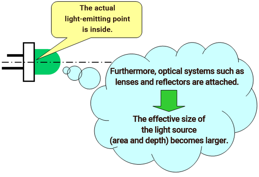
When measuring the luminous intensity of an LED, the reference distance is straightforward for bare chip LEDs, where the light source is the chip surface itself. However, packaged LEDs often use lenses or reflectors, which increase the effective size (area and depth) of the light source. As a result, it is unclear whether the reference point for distance should be the chip surface, the apex of the package, or somewhere in between.
To address this, measurements should be performed with the distance set as far as practical. This minimizes the impact of the uncertainty in the light source's position—even if the package apex is arbitrarily used as the reference point. By increasing the distance, errors introduced by the ambiguous light source position can be reduced to negligible levels.
≪5≫ Determining the true light-sensing surface position
Annex 4 of JIS C 1609-1:2006 (Illuminance Meters – Part 1: General Measuring Instruments) provides a detailed explanation of how to determine the "true light-sensing surface position" for illuminance meters. This section is included as a reference guide, specifically outlining methods for identifying the precise location of the effective light-sensing surface.