Theory of Light and Color

36. Tips for Using Luminance Meters
In this section, we will explore error factors in luminance meter measurements caused by user operation. Similar to illuminance meters, measurement errors in luminance meters can arise from two primary sources: hardware-related issues and user-handling errors.
Luminance is the perceived luminous intensity [cd] per unit area [m2], measured as [cd / m2]. Luminous intensity is the luminous flux [lm] emitted per unit solid angle [sr], so the unit of luminance can also be expressed as [lm / (m2·sr)]. (See Chapter 7)
(1) Proper Focus is Crucial
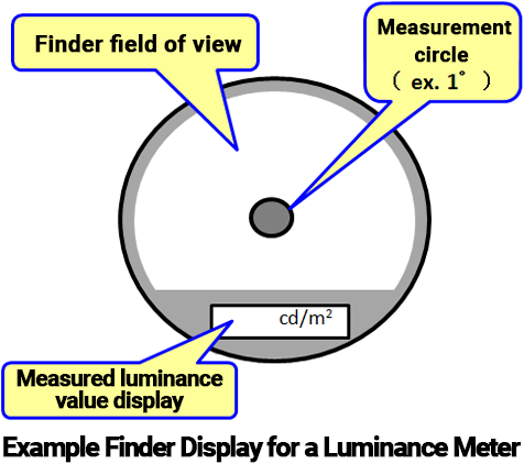
The finder on a luminance meter captures the surrounding area of the measurement site, allowing you to locate the target measurement spot and adjust the focus accordingly. When using the luminance meter, align the measurement circle in the center of the viewfinder with the measurement site, focus it, and then press the measurement button to take the reading. ≪1≫ In this way, the luminance meter only measures the luminous flux emitted from the area within the measurement circle in the finder, traveling toward the observation direction. This method ensures that measurements are taken in line with the definition of "luminous flux per unit area (as seen from the observation direction)." If the focus is not properly adjusted on the measurement area, unwanted luminous flux from outside the measurement area will mix into the reading, resulting in measurement errors. ≪2≫ This is similar to how an out-of-focus photograph becomes blurry when the camera's focus is not set correctly.
The focus of the luminance meter is adjusted by rotating the lens's distance ring. However, if the measurement site is too close, even turning the distance ring to its closest setting might not align the focus. In such cases, accurate luminance measurement is not possible. Some luminance meters come with a close-up lens as an accessory, which can help adjust the focus at shorter distances within the close-up lens's specified range.
(2) Measuring Areas with Uneven Luminance Distribution
Luminance meters typically measure light within a narrow angle, meaning that the area of the measurement site is quite small. Thus, they are relatively affected by changes in luminance distribution near the measurement site. However, significant unevenness in the luminance distribution at or near the measurement area could lead to measurement errors. The following points should be kept in mind in such cases:
[1] Keep the Luminance Meter Steady
As mentioned earlier, accurate luminance measurement depends on precisely defining the measurement area. In actual use, especially with handheld luminance meters, it is common for the meter to shake while taking measurements. As a result, the measurement area might shift across the surface, causing a similar effect to a blurry photograph taken with a shaky camera, even if the focus is set correctly.
Minor shaking may not significantly affect the reading if the luminance distribution around the measurement area is nearly uniform. However, if the luminance distribution changes drastically in the surrounding area, it could lead to significant measurement errors. Therefore, it is important to hold the luminance meter steady before taking a measurement.
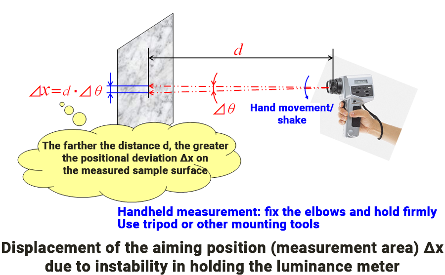
Especially when measuring from a longer distance, the shaking can cause the luminance meter to "scan" the surface, leading to larger errors due to the overall unevenness of the luminance distribution. To eliminate the risk of shaking, consider mounting the luminance meter on a tripod or camera stand. ≪3≫
[2] Uneven Luminance Distribution Yields Area-Weighted Average
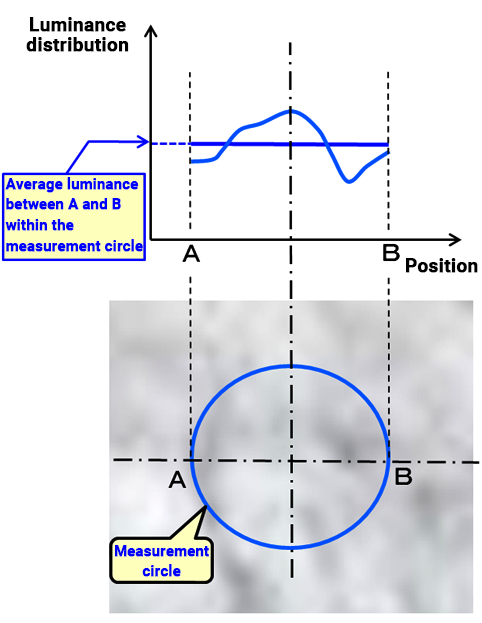
The luminance meter's optical system measures light from a narrow area, often indicated by a small measurement circle (e.g., 1°). While the luminance distribution within the measurement area is usually uniform, there can be bumps or unevenness. In such cases, the measurement will reflect the area-weighted average of the luminance distribution. Therefore, it's important to understand that if the measurement area is subdivided more finely, parts of the area may have higher or lower luminance than the overall measurement result.
If you're concerned about uneven luminance distribution within the measurement area and want to inspect it closely, shorten the measurement distance (i.e., set the lens's distance ring to the nearest setting) to minimize the measurement area. Increasing the number of measurement points will help you more accurately capture the luminance distribution. Additionally, adding a close-up lens can allow you to measure an even smaller area.
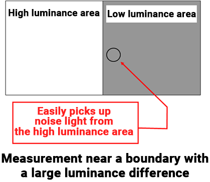
[3] High Luminance Areas Near the Measurement Site
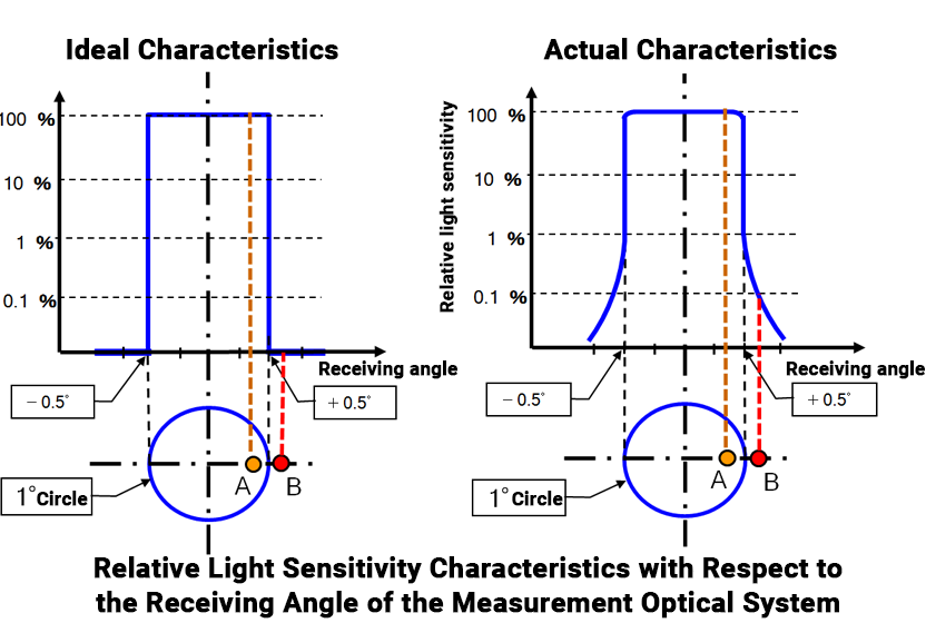
The luminance meter’s optical system is designed to measure only light from within the indicated measurement circle in the finder. ≪1≫ The sensor’s sensitivity is theoretically uniform within the measurement circle and zero outside of it. In reality, the sensitivity gradually decreases at the outer edge of the circle, as shown in the right diagram below.
For typical smooth luminance distribution surfaces, this issue is generally negligible. However, if you are measuring near a boundary between a high-luminance and a low-luminance area, the decreased sensitivity at the boundary could lead to measurement errors.
If you assume the relative sensitivity of the outer edge (B) is 0.1% compared to the measurement circle sensitivity (A). If the luminance of area B is the same as area A, the effect is almost negligible. However, if the luminance of B is 1,000 times higher than A, the measurement from B will interfere with the reading of A.
Thus, when measuring near a boundary between high and low luminance areas, be aware that light from the high luminance area could affect your reading. If you suspect the luminance distribution in the low luminance area is relatively uniform, it is safer to take measurements further away from the high-luminance boundary.
(3) Luminance and Measurement Distance
As discussed in Chapter 9, luminance is often considered independent of the measurement distance. However, this is true only when certain conditions are met, and these conditions are often overlooked. Please refer to the note in Chapter 9, Comment ≪6≫ for more details.
In an ideal scenario, the measurement distance would not affect luminance readings, but real-world measurement conditions can vary. Because of this, ideal conditions may not always be met, and luminance values can change slightly depending on the distance. To ensure the accuracy and reproducibility of measurements in such cases, record the measurement distance for reference.
(4) Application of Luminance Meters to Illuminance Measurements
This section is not about general precautions when using a luminance meter, but instead about how a luminance meter can be used to avoid illuminance measurement errors, which we discussed in the previous chapter.
As explained in Chapter 10, there is a proportional relationship between the illuminance from incident light on a reflective surface and the luminance from the reflected light. Therefore, this relationship can be used to measure illuminance with a luminance meter. However, certain conditions must be met, including knowing the diffuse reflection distribution and reflectance characteristics of the reflective surface in advance. Unfortunately, these characteristics are usually unknown and vary depending on the type of reflective surface (e.g., material, surface texture) and the incident and reflection angles. This makes it difficult to apply the relationship directly in most cases.
An optical product called a standard white reflective plate can help overcome these challenges. A standard white reflective plate has excellent uniform diffuse reflection characteristics (similar to a theoretically perfect diffuse reflective surface) and a high reflectance rate (typically over 90%). If the illuminance on this reflective surface due to incident light is E [lx] and the luminance from the reflected light is L [cd/m²], the following relationship holds:
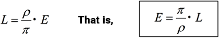
Where ρ represents the reflectance (or more precisely, the luminance factor: see Chapter 12, Comment ≪1≫ )of the standard white reflective plate. The specific data for a plate's characteristics are included when buying the plate. Theoretically, this relationship holds on a perfectly uniform diffuse reflective surface regardless of the incident (illumination) angle or the observation (reflection) angle. Thus, you can calculate illuminance E by measuring the luminance L from any direction.
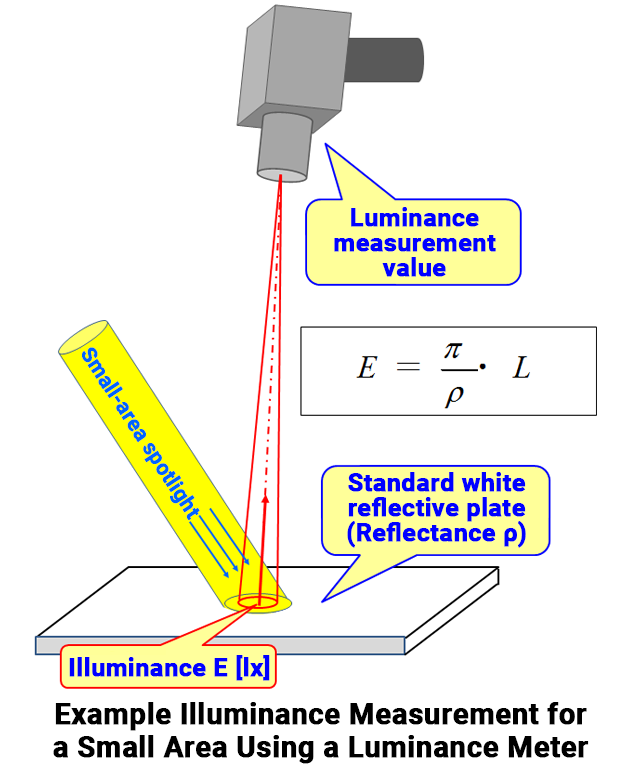
Last chapter (Chapter 35), we discussed that when measuring illuminance in areas smaller than the illuminance meter's detection area, it is difficult to achieve accurate measurements due to the uneven distribution of sensitivity within the detection area. In such cases, you can measure the illuminance of smaller areas by using a luminance meter with a standard reflective plate. The luminance meter, which has a very narrow detection angle, can measure the luminance of a small area on the reflective surface. Illuminance can be calculated by placing the standard white reflective plate at the desired measurement location, measuring the luminance of that small area with the luminance meter, and applying the relationship above.
While the luminance should theoretically be the same from any reflection angle on a uniform diffuse reflective surface, real-world standard white reflective plates are not perfect. The reflectance in the direct reflection direction is slightly higher than in nearby reflection directions, so it is better to avoid measuring luminance in the direct reflection direction.
Comment
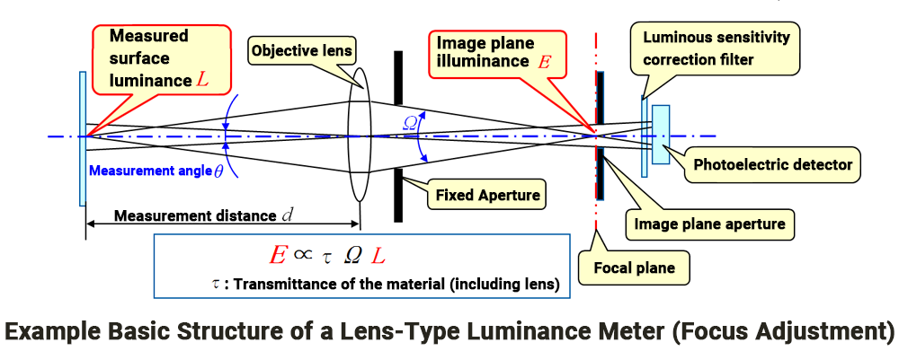
≪1≫ Basic configuration example of a luminance meter (lens-type with filter)
A lens-type luminance meter forms an image of the measured surface using an objective lens. The image is then focused onto the image plane. A diaphragm is used to allow only light from the measured area to pass through and reach the sensor unit, which consists of a visual sensitivity correction filter and a photodetector.
When the focus is correctly adjusted, the illuminance on the image plane (E) is proportional to the luminance (L) of the measured surface (E ∝ τ Ω L). Therefore, by measuring the image plane illuminance (E), the luminance (L) can be calculated. Here, Ω represents the angular spread (solid angle) of the luminous flux incident on the image plane diaphragm, and τ is the transmittance of the medium which includes the lens and the path from the measured surface to the sensor unit.
Simply focusing the image using the lens causes the image plane illuminance (E) to change due to the variations in the solid angle (Ω) and transmittance (τ). When the objective lens is moved forward or backward to adjust the focus, the solid angle (Ω) of the luminous flux incident on the sensor unit will change. To keep the solid angle constant, a fixed aperture is placed immediately after the objective lens, and combined with the image plane diaphragm, this ensures that the solid angle (Ω) remains constant.
Regarding transmittance (τ), although it may change under specific conditions (such as streetlights in fog or underwater lighting in aquariums), it is considered constant under normal measurement conditions. Therefore, under typical conditions, the image plane illuminance (E) and luminance (L) are in a simple proportional relationship.
≪2≫ Focus adjustment and measurement error in lens-type luminance meters
At a measurement distance (d1), when the focus is correctly adjusted, the measured area is focused onto the image plane diaphragm (fixed aperture) located at the front of the sensor unit. This means that from the perspective of the luminance meter's sensor, only the area of the measured surface is visible through the image plane diaphragm and fixed aperture when the focus is perfectly aligned.
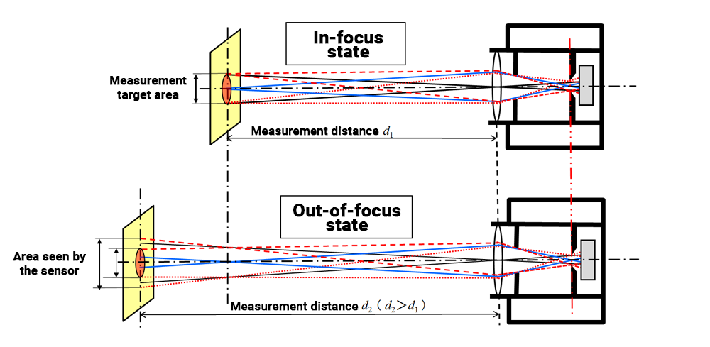
However, if the distance adjustment remains fixed and, for example, the measured surface is at a farther distance (d2), it causes the focus to shift. As a result, the area of the measured surface seen from the sensor will be larger than it was at the original distance (d1). The luminous flux from outside the intended measurement area will mix into the measurement, causing errors.
≪3≫ Tripod mounting
Some luminance meter models have a tripod screw hole on the underside of the grip.