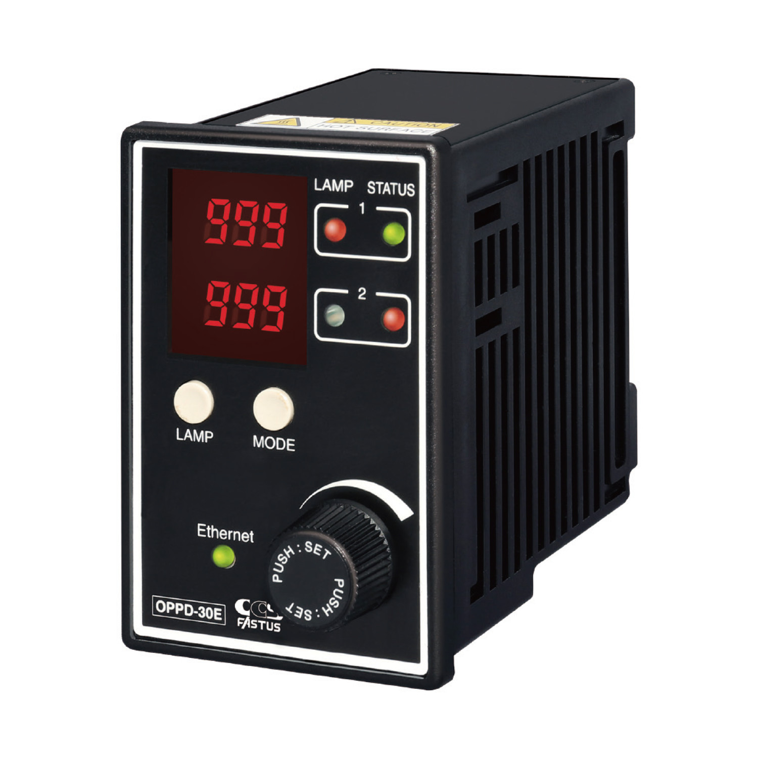
OPPD-30E
Features
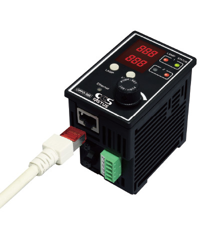
Simple light intensity and ON/OFF control through Ethernet communication Connecting is simple.
Just plug in a LAN cable!
With support for DHCP, the OPPD-30E automatically obtains IP addresses and other information necessary for connection.
Manual configuration of network settings required with conventional models is unnecessary, and communication can be easily established simply by connecting a LAN cable within a DHCP server network environment.

High-speed communication
With the OPPD-30E, light intensity values can be rewritten for both channels in about 6 ms.
- OPPD-30E : Approx. 6 ms / 2 ch
- Conventional Optex FA models : Approx. 11 ms / 2 ch
- Other manufacturer products or equivalent : Approx. 18 ms / 1 ch
Simple PC software-based setup
Dedicated PC software is available for the OPPD-30E. This software can be used to configure light intensity, ON/OFF control and frequency, among other aspects. brAccess the Optex FA homepage to download the software for free.
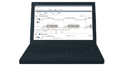
- Intuitively operable interface
The software interface has been developed so that light intensity and ON/OFF control can be seen at a glance.
Settings can be easily configured through pull-down menus or through direct input.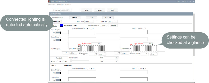
*Screen content and layout subject to change.
- Configurable settings
- PWM frequency
- Illumination control input selection
- Light intensity value/Light emission width
- Lighting delay time
- Feedback
- Monitor brightness alarm, etc.
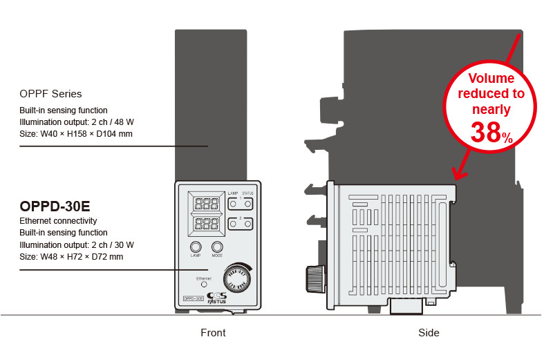
Compact size
Thanks to high-density mounting technology and an optimuml heat dissipation design, the OPPD-30E boasts a size just 38% that of OPPF Series products.
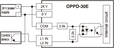
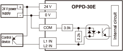
Connection to external device (illumination control)
With NPN open collector output device
With PNP open collector output device
New lighting control features
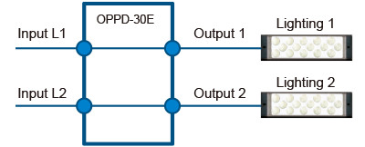
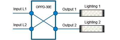
Illumination control input allocation function
With conventional models, one lighting output is allocated per controller input.
With the OPPD-30E, users can switch between one or two lighting units for every input at the controller.
In addition to reducing the number of wiring, the OPPD-30E enables flexible input changes even after wiring has been completed.
Conventional setup
Allocation examples
Ex. 1: Simultaneous output to 2 channels for 1 input
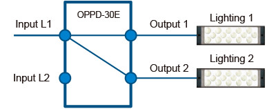
Ex. 2: Switchable output
Lighting control sequence
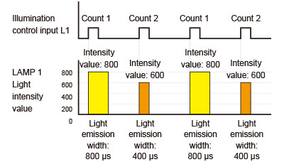
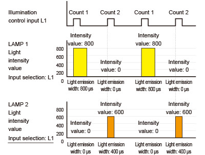
With the OPPD-30E, up to four illumination setting patterns including light intensity values can be configured. Each pattern can be configured in an illumination control sequence with ordered switching for each illumination control input. (Lighting delay time settings are shared.) With intensity values and illumination widths set in advance, automatic switching is only performed for illumination control input, allowing the time required for changing settings to be kept to a minimum.
With conventional models, control is not possible without using a PLC and setting up complex ladders.
With the OPPD-30E, such control can be achieved with no other equipment required.
Ex. 1: Light intensity value and emission width switching
Lighting control sequence: 2-count setting
Ex. 2: Lighting switching
Lighting control sequence: 2-count setting
Automatic brightness management and predictive lighting maintenance
Brightness/temperature monitoring and feedback control

Connecting the OPPD-30E to lighting equipped with “FALUX sensing” enables monitoring of the lighting brightness and temperature.
Based on these monitored values, light intensity feedback control can be performed, allowing brightness to be kept constant.
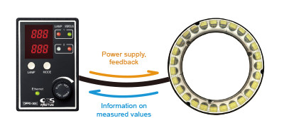
- Monitoring function
The lighting’s built-in photodiodes are used to monitor the brightness of the lighting.
Alarm output: Setting a threshold in advance makes it possible to output an alarm when brightness decreases to a predetermined level.
Instrumental error adjustment: Absolute brightness monitoring makes it possible to adjust for lighting instrumental errors. - Light intensity feedback control
Automatic brightness management
With LED lighting, decreases in brightness can occur due to various factors including drops in voltage caused by extension cables
and LED deterioration.
The factory default brightness is maintained through automatically corrected intensity values to prevent drops in brightness.
Corrections can be verified as “Corrected intensity value.”
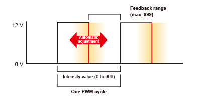
The feedback range is determined by the set intensity value and the maximum intensity value (999).
A signal is output as a feedback error when the maximum intensity value is reached.[Feedback mechanism]
OPPD-30E
The PWM ON time is corrected according to changes in brightness, allowing brightness to be automatically adjusted.
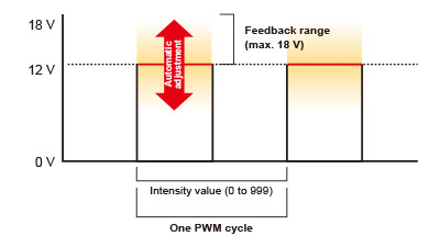
<Reference> OPPF Series
Output voltage is corrected according to changes in brightness, allowing brightness to be automatically adjusted.
Measured brightness/temperature logging function
Measured values such as brightness and temperature can be collected and displayed in a graph using the dedicated software (PC).
Data can be output as a .csv file. Displaying monitored values allows users to recognize LED degradation. This feature is useful as a function for predictive lighting maintenance.
- Recordable items
- Light intensity value
- Monitored value
- Corrected intensity value
- Lighting temperature
- Controller temperature
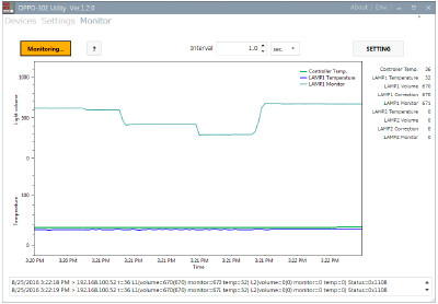
Monitor screen
(dedicated software)
Products
-
Machine Vision Applications
Ring
Low-angle Ring
Waterproof Ring
Bar (Area)
Low-angle Square
Flat
Flat Dome
Line Pattern
Dome
Coaxial
Cylinder
High Power Strobe
UV Lights [Ultraviolet Lighting] / Violet Light
IR Lights [Infrared Lighting] (under 1000nm)
IR Lights [Infrared Lighting] (over 1000nm)
Spot
Fiber Heads
Light Source Unit
Line (Convergent Lighting)
Line (Diffused Lighting)
Line (Oblique Angled Lighting)
Lights for Fringe Interference Inspection
Reference Light Source
Custom Order Product
Intensity Control Units [Light Units with Intensity Control Unit ]
Effilux Products
Basler Camera Light Series
- BCL Series (Bar Light)
- BCR Series (Ring Light)
- BCBL Series (Flat Light)
- BCF Series (Flood Light)
- BCL Series (Bar Light) Diffusion Plates
- BCR Series (Ring Light) Diffusion Plates
- BCF Series (Flood Light) Transparent Plate
- BCL Series (Bar Light) Light Polarizing Plates
- BCR Series (Ring Light) Polarizing Plates
- BCF Series (Flood Light) Polarizing Plates
- BCR Series (Ring Light) Light Adapter
- BCL Series (Bar Light) Light Bracket
- Basler Camera Light dedicated cable
-
Control Units
Digital Control Units
Strobe Unit
High Power Strobe Control Unit
PoE Enabled Controller
Controller with EtherNet/IP Interface
LED Light Controller
Control Units [for the HLV Series]
High-capacity Constant-current Control Units
High-capacity Analog Control Unit
Other Control Units
-
Cables
Straight Cables
2-way Cables
4-way Cables
Robot Cables
2-way Robot Cables
4-way Robot Cables
Straight Cables [EL connector type]
2-way Cables [EL connector type]
Extension Cable [for PF Series]
Straight Cables for metal connector (7 pins)
Straight Cables for metal connector (37 pins)
Straight Cables for M12 connector
External Control Cables
Relay Connector
AC Power Cable
-
Options
Filters
Diffusion Plates
- Diffusion Plates [for Ring Lights]
- Diffusion Plates [for LDR-PF Series]
- Diffusion Plates [for LDR-PF-LA Series]
- Diffusion Plates [for Low-angle Ring Lights]
- Diffusion Plates [for Bar Lights]
- Diffusion Plates [for LDL-PF Series]
- Diffusion Plates [for HLDL3 Series]
- Diffusion Plates [for LB Series]
- Diffusion Plates [for Coaxial Lights]
- DF Series
- DF80 Series
Polarizing Plates
- Polarizing Plates [for Ring Lights]
- Polarizing Plates [for LDR-PF Series]
- Polarizing Plates [for Bar Lights]
- Polarizing Plates [for LDL-PF Series]
- Polarizing Plates [for HLDL3 Series]
- Polarizing Plates [for LB Series]
- Polarizing Plates [for Coaxial Lights]
- Polarizing Plates [for IR Series Infrared Lights (over 1000-nm type)]
- PL Series (FASTUS)
Light Control Films
Protective Plates
Adapter [for the CSR Series]
Lens Attachment Rings
Fixtures
Fixtures
Converter
Coaxial Units
Reflection Plate
Condenser lens
-
Lenses
Telecentric Lenses
Macro Lenses
-
Software Tools
Program for controllers
Version Upgrade for controllers
Application note for controllers
-
Agri-Bio Lighting
LED Light Units for Plant Research
ISL-150X150 Series Unit
ISL-150X150 series cables
-
Human Vision Inspection and Microscope Applications
LED Light Units for Microscopes
 Request Free Trial
 Request Quotation
 Inquiry Form
 Locations