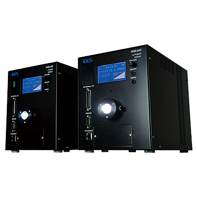
[Discontinued] PFBR-600 Series
Features and Functions
Provides High Output to Easily Replace Xenon Flash Light Sources
Output increased more than 8x that of previous LED light sources. The result is an ultra-high output light source unit comparable to xenon flash light sources.
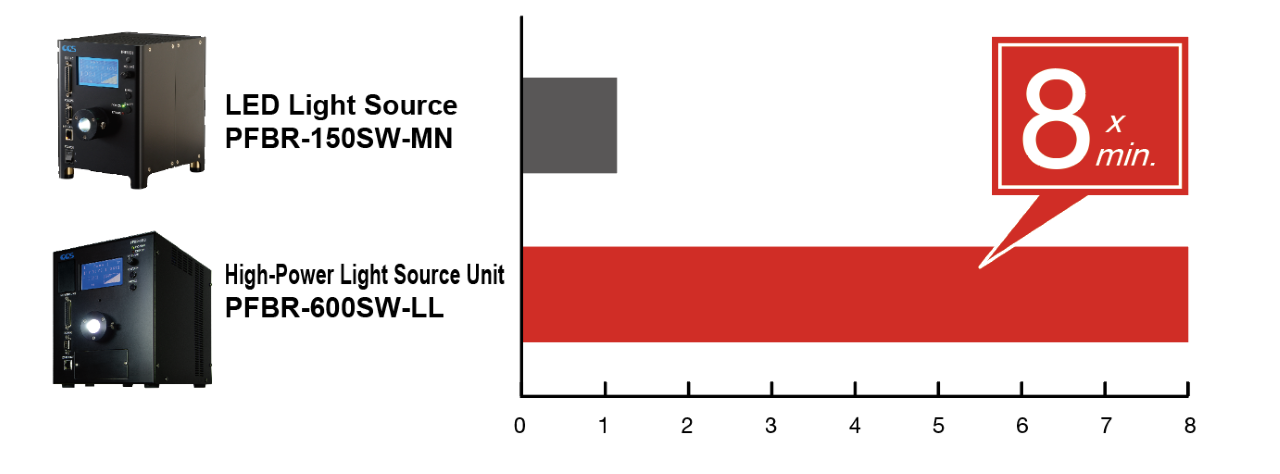
*1 Actual measurement values with intensity of 100%, a bundle of Φ8 mm, a straight light guide with a total length of 1,000 mm installed, and at a position 50 mm away from the fiber output edge.(Results may vary for individual units.)
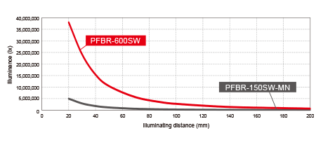
*2 Actual measurement values with intensity of 100%, bundles of Φ8 mm, a straight light guide with a total length of 1,000 mm installed, and at positions at each illuminating distance away from the fiber output edge.(Results may vary for individual units.)
High-Speed Response 1 μs or Faster
For pulse illumination synchronized to external trigger input.
Response Time by External Trigger Signal Input *3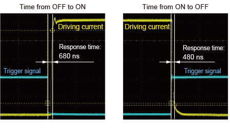
*3 Measured at the maximum light quantity.This data is for reference only. Actual values may vary.
Characteristics/Data
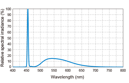
Light Spectrum Characteristics *4
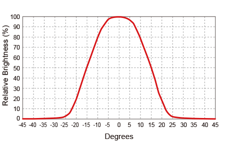
Distribution Characteristics of Fiber Output Edge*5
*4 Actual measurement values using our measurement conditions.Results for individual products may vary.
*5 Actual measurement values with intensity of 100%, a bundle of Φ8 mm, a straight light guide with a total length of 1,000 mm installed, and at a position 1,000 mm away from the fiber output edge. (Results may vary for individual units.)
Functions
Equipped with Linearity Adjustment Function
Linearity with reproducibility is achieved with our unique correction function.
Light Intensity is Adjustable with a High Resolution of 1,024 Steps. *6
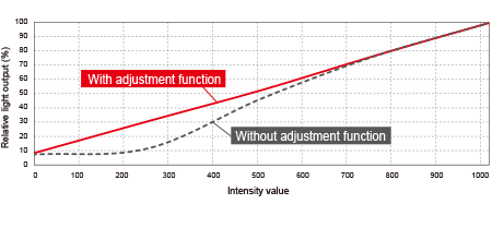
*6 Actual measurement values using our measurement conditions. Results for individual products may vary.The correction function on this product is permanently enabled.
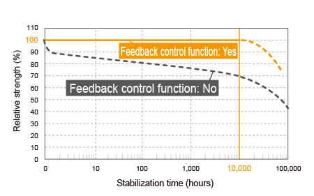
Equipped with Light Quantity Feedback Control Function
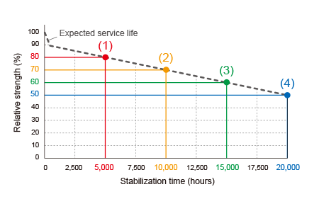
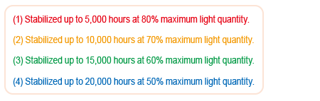
Use the light quantity feedback control function and set the desired stabilization time to maintain output over long periods.
Comparison of Relative Strength According to Light Quantity Feedback Control Function (Representative) *7
Relationship between Light Quantity Feedback Control Function and Stabilization Time (Representative) *8
* Refer to the instruction guide for more information on the light quantity feedback control function.
*7 When the stabilization time is set to 10,000 hours.This graph is representative of the function. Actual values may vary.
*8 In Ta=40°C environment.This graph is representative of the function. Actual values may vary.
Easily Checked Operating Status on the LCD Panel
Displays operating status such as Light source temperature, internal temperature and operating time.
Operation Display 1
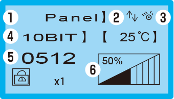
- (1) Operating mode
- (2) Feedback function icon
- (3) Light ON icon
- (4) Intensity resolution
- (5) Intensity value
- (6) Intensity indicator
Operation Display 2
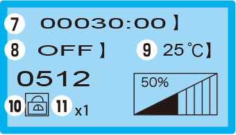
- (7) Total time (min.)
- (8) Strobe setting
- (9) Light source temperature
- (10) Lock icon
- (11) Intensity step magnification
When you press the operating knob, the display of the magnification will change in the following order :x1, x10, and x100.
Mode Setting Display
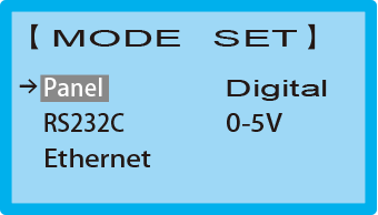
* Refer to the instruction guide for details of displayed contents.
External Control by Use of a Large Variety of Communication Methods
- Ethernet communication control: TCP/IP and UDP/IP
- Serial communication control: RS-232C
- Parallel communication control
Digital light control: Compatible with sink and source types
Analog light control: Intensity control from 0 to 5 V
Equipped with Linearity Adjustment Function
Linearity with reproducibility is achieved with our unique correction function.
Light Intensity is Adjustable with a High Resolution of 1,024 Steps. *6
*6 Actual measurement values using our measurement conditions. Results for individual products may vary.The correction function on this product is permanently enabled.
Equipped with Light Quantity Feedback Control Function
Use the light quantity feedback control function and set the desired stabilization time to maintain output over long periods.
* Refer to the instruction guide for more information on the light quantity feedback control function.
*7 When the stabilization time is set to 10,000 hours.This graph is representative of the function. Actual values may vary.
*8 In Ta=40°C environment.This graph is representative of the function. Actual values may vary.
Easily Checked Operating Status on the LCD Panel
Displays operating status such as Light source temperature, internal temperature and operating time.
Operation Display 1
- (1) Operating mode
- (2) Feedback function icon
- (3) Light ON icon
- (4) Intensity resolution
- (5) Intensity value
- (6) Intensity indicator
Operation Display 2
- (7) Total time (min.)
- (8) Strobe setting
- (9) Light source temperature
- (10) Lock icon
- (11) Intensity step magnification
Mode Setting Display
* Refer to the instruction guide for details of displayed contents.
External Control by Use of a Large Variety of Communication Methods
- Ethernet communication control: TCP/IP and UDP/IP
- Serial communication control: RS-232C
- Parallel communication control
Digital light control: Compatible with sink and source types
Analog light control: Intensity control from 0 to 5 V
Strobe Model (Custom)
High Power & Dedicated Strobe Operation
PFBR-600SW-LL-XF / PFBR-600SW-LLCF-XF (Custom Model)
For Replacing Xenon Light Sources (PFBR-600 Made-to-order products)
- Next-generation light sources with a maximum brightness of 38 million lux *1
- Maintenance free (lamp replacement not required)
- Strobe lighting mode (internal trigger mode, external trigger mode) can be selected
- External control via EtherNet, parallel or serial communication
- Dimming setting in up to 1,024 levels (10 bit: 1,024 levels / 8 bit: 256 level)
Measured value at an irradiation distance of 20 mm from the fiber outer end face (not a guaranteed value)

This is a made-to-order product. For queries and details, contact your CCS sales representative.
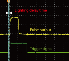
Stable light emission compared to xenon light source
There is no jitter and no light leakage like a xenon flash lamp.
The lighting waveform is a square wave and can control the lighting cycle with a duty ratio of 1% or less using pulse width modulation (PWM).
Comparison of pulse output with xenon light source
PFBR-600SW-LL-XF
Xenon light source
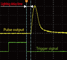
Note: Actual values under our measurement conditions. The data included is for reference only. Actual values may vary.
Characteristics/Data
Light Spectrum Characteristics *3
Distribution Characteristics of Fiber Output Edge*4
*3 Actual measurement values using our measurement conditions.Results for individual products may vary.
*4 Actual measurement values with intensity of 100%, a bundle of Φ8 mm, a straight light guide with a total length of 1,000 mm installed, and at a position 1,000 mm away from the fiber output edge. (Results may vary for individual units.)
Intensity Switching Model (Custom)
High Power & High Speed Switching
PFBR-600SW-LL-HD / PFBR-600SW-LLCF-HD (Custom Model)
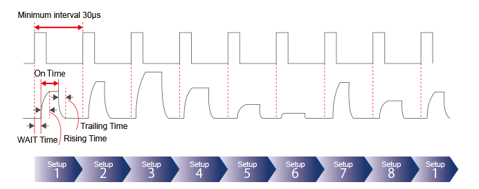
By applying preset light intensity values in a sequence according to the trigger input, it is possible to change light intensity at high speed (2 - 8 patterns). It is suited for inspections where the workpiece surface has differing reflectivity or transparency.
This is a made-to-order product. For queries and details, contact your CCS sales representative.
Workpiece sample of electrode sheet
(same workpiece under different light intensity set for each trigger input)
Triger 1 / Light Intensity:40
Triger 2 / Light Intensity:70
Triger 3 / Light Intensity:100
Triger 4 / Light Intensity:130
Triger 5 / Light Intensity:160
Triger 6 / Light Intensity:190
Triger 7 / Light Intensity:230- ss="col-md-3 marB1">
Triger 8 / Light Intensity:255
Timing Chart
Filter Changer
PFBR-600SW-LLCF / PFBR-600SW-LLCF-XF / PFBR-600SW-LLCF-HD
Filter Changer Model
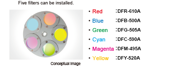
Use color filters to emit light at specific wavelengths.
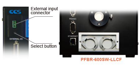
- Equipped with a multi-filter changer that holds five filters.
- Filters can be changed manually and using external communication.
- Easily replace filters by removing the front cover.
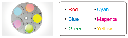
- Filters available in six colors.
A variety of filters are available with excellent heat resistance.
Options
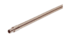
Light Guides / Light Guide Adapters
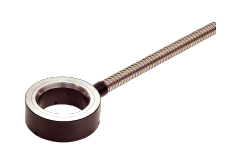
We offer various light guides suited to a variety of applications, including straight types, ring types, and types for line sensors.
Straight Type
Ring Type
Bar Type for Line Sensors
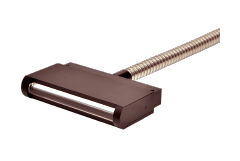
Light Guide Adapter
(AD-PFBR-600-01)
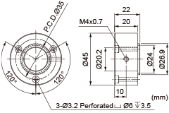
- Please be aware that the light guide adapter must be installed after purchase by the customer.
- For light guide adapters other than AD-PFBR-600-01, please ask CCS.
- We accept custom orders for the light guides. Please contact your CCS sales representative for details.
Color Filters
Use filters to emit the optimum light for the inspected workpiece.
Available Six Colors (Five filters can be installed.)
External Control Cables
Select an appropriate cable, depending on the communication method.
EXCB2-25M-3
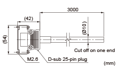
- Parallel communication cable(Compatible with digital and analog intensity control)
- Purchase a commercially available RS-232 crossover cable (length: 3 m max.) for the serial communication cable.
- Purchase a commercially available LAN cable (length: shorter than 30 m) for the Ethernet communication cable. Refer to the instruction guide for more information.
Products
-
Machine Vision Applications
Ring
Low-angle Ring
Waterproof Ring
Bar (Area)
Low-angle Square
Flat
Flat Dome
Line Pattern
Dome
Coaxial
Cylinder
High Power Strobe
UV Lights [Ultraviolet Lighting] / Violet Light
IR Lights [Infrared Lighting] (under 1000nm)
IR Lights [Infrared Lighting] (over 1000nm)
Spot
Fiber Heads
Light Source Unit
Line (Convergent Lighting)
Line (Diffused Lighting)
Line (Oblique Angled Lighting)
Lights for Fringe Interference Inspection
Reference Light Source
Custom Order Product
Intensity Control Units [Light Units with Intensity Control Unit ]
Effilux Products
Basler Camera Light Series
- BCL Series (Bar Light)
- BCR Series (Ring Light)
- BCBL Series (Flat Light)
- BCF Series (Flood Light)
- BCL Series (Bar Light) Diffusion Plates
- BCR Series (Ring Light) Diffusion Plates
- BCF Series (Flood Light) Transparent Plate
- BCL Series (Bar Light) Light Polarizing Plates
- BCR Series (Ring Light) Polarizing Plates
- BCF Series (Flood Light) Polarizing Plates
- BCR Series (Ring Light) Light Adapter
- BCL Series (Bar Light) Light Bracket
- Basler Camera Light dedicated cable
-
Control Units
Digital Control Units
Strobe Unit
High Power Strobe Control Unit
PoE Enabled Controller
Controller with EtherNet/IP Interface
LED Light Controller
Control Units [for the HLV Series]
High-capacity Constant-current Control Units
High-capacity Analog Control Unit
Other Control Units
-
Cables
Straight Cables
2-way Cables
4-way Cables
Robot Cables
2-way Robot Cables
4-way Robot Cables
Straight Cables [EL connector type]
2-way Cables [EL connector type]
Extension Cable [for PF Series]
Straight Cables for metal connector (7 pins)
Straight Cables for metal connector (37 pins)
Straight Cables for M12 connector
External Control Cables
Relay Connector
AC Power Cable
-
Options
Filters
Diffusion Plates
- Diffusion Plates [for Ring Lights]
- Diffusion Plates [for LDR-PF Series]
- Diffusion Plates [for LDR-PF-LA Series]
- Diffusion Plates [for Low-angle Ring Lights]
- Diffusion Plates [for Bar Lights]
- Diffusion Plates [for LDL-PF Series]
- Diffusion Plates [for HLDL3 Series]
- Diffusion Plates [for LB Series]
- Diffusion Plates [for Coaxial Lights]
- DF Series
- DF80 Series
Polarizing Plates
- Polarizing Plates [for Ring Lights]
- Polarizing Plates [for LDR-PF Series]
- Polarizing Plates [for Bar Lights]
- Polarizing Plates [for LDL-PF Series]
- Polarizing Plates [for HLDL3 Series]
- Polarizing Plates [for LB Series]
- Polarizing Plates [for Coaxial Lights]
- Polarizing Plates [for IR Series Infrared Lights (over 1000-nm type)]
- PL Series (FASTUS)
Light Control Films
Protective Plates
Adapter [for the CSR Series]
Lens Attachment Rings
Fixtures
Fixtures
Converter
Coaxial Units
Reflection Plate
Condenser lens
-
Lenses
Telecentric Lenses
Macro Lenses
-
Software Tools
Program for controllers
Version Upgrade for controllers
Application note for controllers
-
Agri-Bio Lighting
LED Light Units for Plant Research
ISL-150X150 Series Unit
ISL-150X150 series cables
-
Human Vision Inspection and Microscope Applications
LED Light Units for Microscopes
 Request Free Trial
 Request Quotation
 Inquiry Form
 Locations